
Intel Pentium 4 Processor in the 478-Pin Package Thermal Design Guidelines

Intel
®
Pentium
®
4 Processor in the 478-Pin Package Thermal Design Guidelines
R
Design Guide 19
2.3 Thermal Metrology for the Intel
®
Pentium
®
4
Processor in the 478-Pin Package
2.3.1 Processor Cooling Solution Performance Assessment
Section 2.3 discusses guidelines for testing thermal solutions, including measuring processor
temperatures. In all cases, power dissipation and temperature measurements must be made to
validate a cooling solution.
Thermal performance of a processor heatsink in a chassis should be assessed using a thermal test
vehicle (TTV) provided by Intel (refer to section 2.3.4). TTV is a well-characterized thermal tool;
using real parts introduces other factors that can impact test results. In particular, the power level
from real processors varies significantly, even when running the MaxPower application provided
by Intel, due to variances in the manufacturing process. The TTV provides consistent power and
power density for thermal solution characterization and result can be easily translated to real
processor performance. Accurate measurement of the power dissipated by a real processor is
beyond the scope of this document.
Once the thermal solution and chassis are designed and validated with the TTV, it is recommended
to verify functionality of the thermal solution on real processors and on fully integrated systems
(see section 2.4). The Intel thermal stressing software MaxPower enables steady power dissipation
on a processor to assist in this testing.
Contact your Intel field sales representative for the version of MaxPower that applies to the
processor.
2.3.2 Local Ambient Temperature Measurement Guidelines
The local ambient temperature T
A
is the temperature of the ambient air surrounding the processor.
For a passive heatsink, T
A
is defined as the heatsink approach air temperature; for an actively
cooled heatsink, it is the temperature of inlet air to the active cooling fan.
It is worthwhile to determine the local ambient temperature in the chassis around the processor to
understand the effect it may have on the case temperature.
T
A
is best measured by averaging temperature measurements at multiple locations in the heatsink
inlet airflow. This method helps reduce error and eliminate minor spatial variations in temperature.
The following guidelines are meant to enable accurate determination of the localized air
temperature around the processor during system thermal testing.
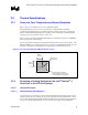
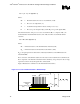
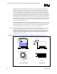
For active heatsinks, it is important to avoid taking measurement in the dead flow zone that
usually develops above the fan hub. Measurements should be taken at four different locations
uniformly placed at the center of the annulus formed by the fan hub and the fan housing to
evaluate the uniformity of the air temperature at the fan inlet. The thermocouples should be placed
approximately 0.1 to 0.3 inch (2.54 mm to 7.62 mm) above the fan hub vertically, and halfway
between the fan hub and the fan housing horizontally as shown in Figure 3. Using an open bench
to characterize an active heatsink can be useful, and usually ensures more uniform temperatures at
the fan inlet. However, additional tests that include a barrier above the test motherboard surface