
Intel Pentium 4 Processor in the 478-Pin Package Thermal Design Guidelines

Intel
®
Pentium
®
4 Processor in the 478-Pin Package Thermal Design Guidelines
R
20 Design Guide
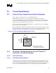
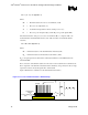
can help evaluate the potential impact of the chassis. This barrier is typically clear Plexiglas*,
extending at least 4 inches in all directions beyond the edge of the thermal solution. Typical
distance from the motherboard to the barrier is 3 inches (76.2 mm) to 3.5 inches (88.9 mm). For
even more realistic airflow, the motherboard should be populated with significant elements like
memory cards, AGP card, chipset heatsink. If a barrier is used, the thermocouple can be taped
directly to the barrier with a clear tape at the horizontal location as previously described, half way
between the fan hub and the fan housing. If a variable speed fan is used, it may be useful to add a
thermocouple taped to the barrier above the location of the temperature sensor used by the fan to
check its speed setting against air temperature. When measuring T
A
directly in a chassis with a live
motherboard, add-in cards and the other system components, it is likely that T
A
shows as highly
non-uniform across the inlet fan section.
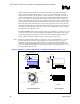
For passive heatsinks, thermocouples should be placed approximately 0.5 to 1.0 inches (12.7 mm
to 25.4 mm) away from processor and heatsink as shown in Figure 3. The thermocouples should
be placed approximately 2 inches (50.8 mm) above the baseboard. This placement guideline is
meant to minimize the effect of localized hot spots from baseboard components.
Note: Testing active heatsink with a variable speed fan can be done in a thermal chamber to cover the
worst-case thermal environment scenarios. Otherwise, when doing a bench top test at room
temperature, the fan regulation prevents the heatsink to operate at its maximum capability. To
characterize the heatsink capability in the worst-case environment in these conditions, it is then
necessary to disable the fan regulation and power the fan directly, after getting direction to do so
from the thermal solution provider.
Figure 3. Guideline Locations for Measuring Local Ambient Temperature (not to scale)
1” to 2”
~0.1” to 0.3”, or
taped to barrier
0.5 to 1.0”
T
A
Air flow
T
A
Air flow
~2”
Plexiglas Barrier
Baseboard
Socket
Processor
Baseboard
Socke
t
Processor
3”
Side View Side View
Top View
Top View
Active Heatsink (with fan) Passive Heatsink