
Intel Pentium 4 Processor in the 478-Pin Package Thermal Design Guidelines

Intel
®
Pentium
®
4 Processor in the 478-Pin Package Thermal Design Guidelines
R
24 Design Guide
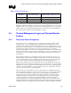
2.3.3.2 Heatsink Preparation – Rectangular (Cartesian) Geometry
To measure the case temperature, a heatsink must be mounted on the processor to dissipate the
heat to the environment. The heatsink base must be grooved to allow a thermocouple to be routed
from the center of the heatsink without altering the IHS for heatsink attachment. The groove in the
heatsink has two features. The first is a 0.180 inch diameter relief for the thermocouple bead and
surrounding epoxy. The second feature is a 0.040 inch-wide groove that allows the thermocouple
wire to be routed to the edge of the IHS/heatsink assembly. The relief and wire routing groove
should be deep enough to avoid significant impact on heatsink performance, while minimizing
interference between thermocouple and the heatsink base. Groove depth should be 0.025 to 0.040
inches maximum [0.6 to 1.0 mm]. Notice the center of the thermocouple bead relief is located
0.050 inches from the centerline of the heatsink. An example of a grooved heatsink base is shown
in Figure 7. It must be noted that the center of the circle area needs to be located 0.05 inches off
center from the location corresponding to the thermocouple bead at the center of the IHS. This
offset accommodates the bead of epoxy that covers both the thermocouple and thermocouple
wires.
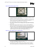
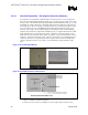
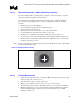
Figure 7. Grooved Heatsink Bottom
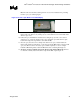
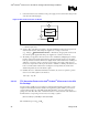
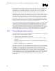
Figure 8. Heatsink Bottom Groove Dimensions
NOTES:
1. Applies to rectangular or cylindrical heatsink base
2. All units are in inches. The groove (including the circle area) depth is 0.025 to 0.040 inches max.