
Intel Pentium 4 Processor in the 478-Pin Package Thermal Design Guidelines

Intel
®
Pentium
®
4 Processor in the 478-Pin Package Thermal Design Guidelines
R
Design Guide 25
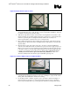
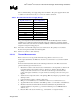
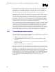
2.3.3.3 Heatsink Preparation – Radial (Cylindrical) geometry
For some heatsinks that have a radial geometry (see Figure 9), it may be necessary to locate the
center of the heatsink using features in the fin pattern.
For example, the 52-fin radial heatsink of the Intel reference design for the Intel
®
Pentium
®
4
processor in the 478-pin package (refer to section 3.3 and Figure 19) requires the following
procedure:
1. Identify fin gap (a) as shown in Figure 9.
2. Count 13 fin gaps in clockwise direction; identify fin gap (b).
3. Repeat for fin gap (c) and fin gap (d).
4. Scribe lines (a-c) and (b-d) across the core area of the radial heatsink.
5. Locate heatsink center at the intersection of lines (a-c) and (b-d).
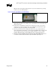
6. Machine a groove 0.040 inches wide, 0.025 to 0.040 inches deep along line (o-a).
7. Locate the center for the circle area 0.050 inches off the heatsink centerline, along line (o-a).
8. Machine the circle area 0.180 inches diameter, 0.025 to 0.040 inches deep to accommodate
the thermocouple and epoxy bead.
Note: This procedure takes into account the fact that the center of the IHS and the center of the heatsink
coincide for this particular design.
Figure 9. Radial Heatsink Geometry
a
b
c
d
o
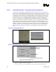
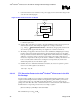
2.3.3.4 Thermal Measurement
1. Attach a thermocouple at the center of the package (IHS-side) using the proper thermocouple
attach procedure (refer to Section 2.3.3.1).
2. Connect the thermocouple to a thermocouple meter.
3. Mill groove on heatsink base (refer to Section 2.3.3.2 or to Section 2.3.3.3).
4. Apply thermal interface material to either IHS top surface or on the surface of heatsink base.
5. Mount the heatsink to the processor package with the intended heatsink attach clip and all
relevant mechanical interface components (e.g. retention mechanism, processor EMI
attenuation solutions, etc.).