
Intel Pentium 4 Processor in the 478-Pin Package Thermal Design Guidelines

Intel
®
Pentium
®
4 Processor in the 478-Pin Package Thermal Design Guidelines
R
26 Design Guide
6. Refer to section 2.3.2 to setup the thermocouples used for T
A
measurement, and connect them
to a thermocouple meter.
7. Depending on the overall experimental setup, the time needed to have stable thermal
conditions may vary. T
A
and T
C
measurements are valid once constant (refer to section
2.3.4.3) for application to the thermal test vehicle).
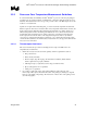
Note: This methodology requires special care when assembling the grooved heatsink on top of the IHS
with the thermocouple attached. Mismatch between the heatsink groove and the thermocouple
wires and bead may lead to inaccurate measurements, and even thermocouple damage, in
particular when compressive load is required to get better performance out of the thermal interface
material.
2.3.4 Thermal Test Vehicle Information
The Intel
®
Pentium
®
4 processor in the 478-pin package Thermal Test Vehicle (TTV) is a FC-
PGA2 package assembled with a thermal test die.
Cooling solution performance should be characterized or validated using the TTV only. Only the
TTV provides a well-characterized tool suitable for thermal testing. TTV. It also allows simulating
processor thermal targets before the parts are available. The correction factor of the TTV to real
processors, given Table 2 below, is then used to define the performance of the solution on real
processor.
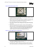
The part number for the TTV is A47244-01.
The TTV can also be identified by the topside marking: ITVN1 THERM SAMP.
2.3.4.1 Thermal Test Die
A resistance-type heater band covers nearly the entire surface area of the test die and is used to
simulate the heat generation on the die.
The room temperature resistance of the heater is about 60 Ω, ±5%. This resistance value will
increase as the die temperature increases at a rate of about 0.10 Ω/
°
C.
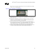
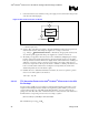
2.3.4.2 Connections
The heater is connected to external pins so that it can be powered by an external DC power supply.
The resistance heater of the thermal die is terminated at the power and ground pins of the package.
The power and ground pin-out of the TTV match the power and ground pin-out of the actual
processor. Therefore the TTV can be plugged into any motherboard that has been designed for the
Intel Pentium 4 processor in the 478-pin package.
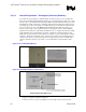
The heater can be accessed by de-populating the power decoupling capacitors and attaching wires
to the power and ground sides of one of the capacitor. It is recommended that all decoupling
capacitors be removed because the high voltages required for the TTV may exceed the maximum
voltage rating of the capacitors. The voltage regulator inductors should also be removed to isolate
the VR from the TTV power supply. Motherboard designs vary; therefore, an optimal location to
tap into power should be chosen by the user.