
Intel Pentium 4 Processor in the 478-Pin Package Thermal Design Guidelines

Intel
®
Pentium
®
4 Processor in the 478-Pin Package Thermal Design Guidelines
R
Design Guide 27
The recommended DC-power supply rating is listed in Table 1. The power supply should be able
to deliver more current if necessary to cover for die resistance variations.
Table 1. Recommended DC Power Supply Ratings
Target Die Power Level Power Supply Rating
20 W 40 V and 1 A
25 W 45 V and 1 A
30 W 45 V and 1 A
35 W 50 V and 1 A
40 W 55 V and 1 A
50 W 60 V and 1.5 A
60 W 65 V and 1.5 A
70 W 70 V and 1.5 A
75 W 75 V and 1.5 A
The power dissipation should be maintained below 75 W and the IHS temperature should be
maintained to less than 80°C during the thermal testing. By violating the constraints, the TTV
lifetime will be reduced. It must be noted that the reliability of TTV is limited and the TTV is not
designed for long-term testing purposes.
Note: The heaters on the thermal testing devices are metal resistors. The polarity does not matter:
Positive and negative terminals are interchangeable.
Note: TTV is not sensitive to static electricity.
2.3.4.3 Thermal Measurements
Refer to Section 2.3.2 for T
A
measurement methodology. Refer to Section 2.3.3.1 for
thermocouple attachment to the IHS and to Section 2.3.3.2 and Section 2.3.3.3 for the heatsink
preparation.
For the thermal measurement itself, use the following instructions for the TTV, instead of the
generic instructions given in Section 2.3.3.4:
1. Measure the resistance of the heater resistor of TTV at the room temperature to check for the
reasonable readings. If reasonable reading of ~60 Ω is not obtained, either the TTV is
damaged or the wire connection is not correct. In case the shortage occurs between the
positive and negative terminals, do not perform the test as damage could occur to the power
supplier.
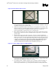
2. Attach a thermocouple at the center of the package (IHS-side) using the proper thermocouple
attach procedure.
3. Connect the thermocouple to a thermocouple meter.
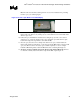
4. Mill groove on heatsink base, as recommended in Section 2.3.3.2 and Section 2.3.3.3.
5. Apply thermal interface materials to either IHS top surface or on the surface of heatsink base.
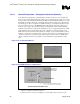
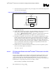
6. Mount the heatsink to the TTV with the intended heatsink attach clip and all relevant
mechanical interface components (e.g., retention mechanism, processor EMI attenuation
solutions, etc.).
7. Place the TTV in the test environment (e.g., a wind tunnel or a computer chassis).