
Intel Pentium 4 Processor in the 478-Pin Package Thermal Design Guidelines

Intel
®
Pentium
®
4 Processor in the 478-Pin Package Thermal Design Guidelines
R
30 Design Guide
added margin may be necessary to ensure the processor silicon does not exceed its maximum
specification (i.e., clock modulation may have to be turned on when the case temperature is
significantly below its maximum specification to ensure the processor does not overheat). This
added margin might have a substantial, and unacceptable, impact on system performance.
Thermal ramp rates, or change in die temperature over a specified time period (∆T/∆t), may be
extremely high in high power processors where ramp rates in excess of 50°C/sec may occur in the
course of normal operation. With this type of thermal characteristic, it would not be possible to
control fans or other cooling devices based on processor case temperature. By the time the fans
have spun up to speed, the processor may be well beyond a safe operating temperature. Just as
large added margins would be necessary to account for package thermal gradients, large margins
would also be necessary if temperature-controlled fans were implemented.
An on-die thermal management feature called Thermal Monitor is available on the Intel
Pentium
4 processor in the 478-pin package. It provides a thermal management approach to support the
continued increases in processor frequency and performance. It resolves the issues discussed
above so that external thermocouples are no longer needed. By using a highly accurate on-die
temperature sensing circuit and a fast acting temperature control circuit, the processor can rapidly
initiate thermal management control. As a result, added thermal margins can be significantly
reduced and the resulting system performance impact can be minimized if not eliminated.
2.4.2 Thermal Monitor Implementation
On the Intel
Pentium
4 processor in the 478-pin package, the Thermal Monitor is integrated into
the processor silicon. The Thermal Monitor includes:
• A highly accurate on-die temperature sensing circuit
• A signal (PROCHOT#) that indicates the processor has reached its maximum operating
temperature
• A thermal control circuit that can reduce processor temperature by controlling the duty cycle
of the processor clocks
• Registers to determine the processor thermal status.
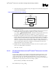
The processor temperature is determined through an analog thermal sensor circuit comprised of a
temperature sensing diode, a factory calibrated reference current source, and a current comparator
(See Figure 11). A voltage applied across the diode induces a current flow that varies with
temperature. By comparing this current with the reference current, the processor temperature can
be determined. The reference current source corresponds to the diode current when at the
maximum permissible processor operating temperature. Each processor is individually calibrated
during manufacturing to eliminate any potential manufacturing variations. Once configured, the
processor temperature at which the PROCHOT# signal is asserted (trip point) is not re-
configurable.