
Intel Pentium 4 Processor in the 478-Pin Package Thermal Design Guidelines

Intel
®
Pentium
®
4 Processor in the 478-Pin Package Thermal Design Guidelines
R
Design Guide 31
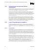
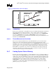
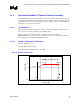
Figure 11. Thermal Sensor Circuit
PROCHOT#
Temperature sensing diode
Reference current source
Current comparator
The PROCHOT# signal is available internally to the processor as well as externally. External
indication of the processor temperature status is provided through the bus signal PROCHOT#.
When the processor temperature reaches the trip point, PROCHOT# is asserted. When the
processor temperature is below the trip point, PROCHOT# is deasserted. Assertion of the
PROCHOT# signal is independent of any register settings within the processor. It is asserted any
time the processor die temperature reaches the trip point The point where the thermal control
circuit goes active is set to the same temperature at which the processor is tested.
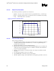
The Thermal Monitor’s thermal control circuit (TCC), when active, lowers the processor
temperature by reducing the duty cycle of the internal processor clocks. The thermal control circuit
portion of the Thermal Monitor must be enabled by the system BIOS for the processor to be
operating within specifications. When active, the TCC turns the processor clocks off and then back
on with a predetermined duty cycle. The actual duty cycle varies from one product to another.
Refer to Figure 12 for an illustration. Cycle times are processor speed dependent and decrease as
processor core frequencies increase.
Performance counter registers, status bits in model specific registers (MSRs), and the PROCHOT#
output pin are available to monitor and control the Thermal Monitor behavior. Details regarding
the use of these registers are described in the IA-32 Intel Architecture Software Developer’s
Manual: Volume III System Programming Guide.
In addition to the Thermal Monitor, the processor clocks can also be modulated via an ACPI
register that is implemented as an MSR on the processor core. This is referred to as ‘on demand
mode’ clock modulation. See section 2.4.3 for additional details.