
Intel Pentium 4 Processor in the 478-Pin Package Thermal Design Guidelines


Intel
®
Pentium
®
4 Processor in the 478-Pin Package Thermal Design Guidelines
R
32 Design Guide
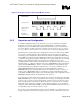
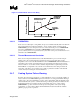
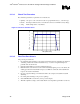
Figure 12. Concept for Clocks under Thermal Monitor Control
PROCHOT#
Resultant
internal clock
Normal clock
Internal clock
Duty cycle
control
2.4.3 Operation and Configuration
To maintain compatibility with previous generations of processors, which have no integrated
thermal logic, the thermal control circuit portion of Thermal Monitor is disabled by default.
During the boot process, the BIOS must enable the thermal control circuit; or a software driver
may do this after the operating system has booted. Refer to the IA-32 Intel Architecture Software
Developer’s Manual: Volume III System Programming Guide for specific programming details.
The thermal control circuit feature can be configured and monitored in a number of ways. OEMs
are expected to enable the thermal control circuit while using various registers and outputs to
monitor the processor thermal status. The thermal control circuit is enabled by the BIOS setting a
bit in an MSR (model specific register). Enabling the thermal control circuit allows the processor
to maintain a safe operating temperature without the need for special software drivers or interrupt
handling routines. When the thermal control circuit has been enabled, processor power
consumption will be reduced within a few hundred clock cycles after the thermal sensor detects a
high temperature (i.e., within a few hundred clock cycles of PROCHOT# assertion). The thermal
control circuit and PROCHOT# go inactive once the temperature has been brought back down
below the thermal trip point, although a small hysteresis (~1 °C) has been included to prevent
multiple PROCHOT# transitions around the trip point. External hardware can monitor
PROCHOT# and generate an interrupt whenever there is a transition from active-to-inactive or
inactive-to-active. PROCHOT# can also be configured to generate an internal interrupt which
would initiate an OEM supplied interrupt service routine. Regardless of the configuration selected,
PROCHOT# will always indicate the thermal status of the processor.
For testing purposes, the thermal control circuit may also be activated by setting bits in the ACPI
MSRs. The MSRs may be set based on a particular system event (e.g., an interrupt generated after
a system event), or may be set at any time through the operating system or custom driver control
thus forcing the thermal control circuit on. This is referred to as “on-demand” mode. Activating
the thermal control circuit may be useful for cooling solution investigations or for performance
implication studies. When using the MSRs to activate the Thermal Monitor feature, the duty cycle
is configurable in steps of 12.5%, from 12.5% to 87.5%.
For any duty cycle, the maximum time period the clocks are disabled is ~3 µs. This time period is
frequency dependent, and decreases as frequency increases. To achieve different duty cycles, the