
Intel Pentium 4 Processor in the 478-Pin Package Thermal Design Guidelines


Intel
®
Pentium
®
4 Processor in the 478-Pin Package Thermal Design Guidelines
R
34 Design Guide
2.4.5 Operating System and Application Software
Considerations
The Thermal Monitor feature and its thermal control circuit work seamlessly with ACPI compliant
operating systems. The Thermal Monitor feature is transparent to application software since the
processor bus snooping, ACPI timer, and interrupts are active at all times.
Activation of the thermal control circuit during a non-ACPI aware operating system boot process
may result in incorrect calibration of operating system software timing loops. The BIOS must
disable the thermal control circuit prior to boot and then the operating system or BIOS must enable
the thermal control circuit after the operating system boot process completes. Refer to the IA-32
Intel Architecture Software Developer’s Manual: Volume III System Programming Guide for
specific programming details.
Intel is working with the major operating system vendors to ensure support for non-execution
based operating system calibration loops and ACPI support for the Thermal Monitor feature. Per
Microsoft, Microsoft* Windows* 98SE and Windows* 2000 use non-execution based calibration
loops and therefore should have no issues with the Thermal Monitor feature. When installing
Windows NT* 4.0, the user must ensure the APIC-based HAL is used. It is expected that other OS
solutions (Linux*, Unix*, etc.) will provide updates to ensure compatibility.
2.4.6 Legacy Thermal Management Capabilities
In addition to Thermal Monitor, the Intel
Pentium
4 processor in the 478-pin package supports
the same thermal management features as available on the Intel Pentium III processor. These
features are the on-die thermal diode and THERMTRIP# signal for indicating catastrophic thermal
failure.
2.4.6.1 Thermal Diode
The Intel Pentium 4 processor in the 478-pin package incorporates an on-die thermal diode, which
can be used with an external device (thermal diode sensor) to monitor long-term temperature
trends. By averaging this data over long time periods (hours/days vs. min/sec), it may be possible
to derive a trend of the processor temperature. Analysis of this information could be useful in
detecting changes in the system environment that may require attention. Design characteristics and
usage models of the thermal diode sensors are described in datasheets available from the thermal
diode sensor manufacturers.
The processor thermal diode should not be relied upon to turn on fans, warn of processor cooling
system failure, or predict the onset of the thermal control circuit. As mentioned earlier, the
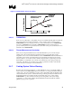
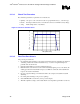
processor high thermal ramp rates make this unfeasible. An illustration of this is as follows. Many
thermal diode sensors report temperatures a maximum of 8 times per second. Within the 1/8
th
(0.125 sec) second time period, the temperature is averaged over 1/16
th
of a second. In a scenario
where the silicon temperature ramps at 50 °C/sec, or approximately 6°C/0.125 sec, the processor
will be ~4.5 °C above the temperature reported by the thermal sensor. (Change in diode
temperature averaged over 1/16
th
seconds = ~1.5°C; temperature reported 1/16
th
second later at
1/8
th
second when the actual processor temperature would be 6°C higher, see Figure 13).