
Intel Pentium 4 Processor in the 478-Pin Package Thermal Design Guidelines

Intel
®
Pentium
®
4 Processor in the 478-Pin Package Thermal Design Guidelines
R
Design Guide 43
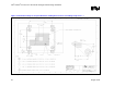
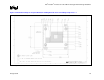
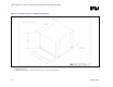
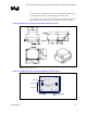
3.2 Enabling Component Mechanical Envelope
Figure 16, Figure 17, and Figure 18 show the overall keep-out and keep-in dimensions for the
reference thermal/mechanical enabling design.
Figure 16 and Figure 17 show the motherboard keep-outs and height restrictions under the
enabling component region. Figure 18 shows the overall volumetric keep-in for the enabling
component assembly. This volumetric space encapsulates the processor, the socket, and the entire
thermal/mechanical enabling solution (for example, for the reference design this includes: fan
heatsink assembly, retention mechanism, and attach clips). The maximum allowable volume for
the fan/heatsink assembly is defined in Section 3.3.2.
Note: Pin A1 and Ball A1, as referred to in Figure 16, do not physically exist on the 478-pin package
and the 478-pin socket respectively. However, they may be used as a reference for design
purposes. Motherboard designers should focus exclusively on Ball A1 callouts to determine
position of the hole respective to the socket when working of the board layout. By design, the
processor is then centered within the hole pattern when the socket is in the closed position. Pin A1
is associated specifically with the package, and its position on the drawing Figure 16 corresponds
to the package within the socket in close position.