
Intel Pentium 4 Processor in the 478-Pin Package Thermal Design Guidelines

Intel
®
Pentium
®
4 Processor in the 478-Pin Package Thermal Design Guidelines
R
48 Design Guide
3.3.2 Heatsink Mechanical Design Guidelines
This section defines the mechanical requirements for the interface between a processor
heatsink /fan /shroud assembly and the reference mechanical components (retention mechanism
and clips). These requirements are intended to support interface control in the design of a custom
thermal solution.
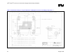
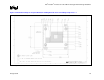
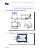
Requirement 1: Heatsink /fan /shroud assembly must stay within the volumetric keep-in defined
Figure 20.
Guideline: Rectangular heatsink base dimensions and tolerances:
X-dimension = 2.70 ±0.010 inch
Y-dimension = 3.28 ±0.010 inch
Z-dimension: Inset in bottom surface of heatsink base in each of four corners
should hold a z-dimension of 0.073 ±0.010 inch.
These dimensions are recommended to limit heatsink movement (rocking and
sliding) during lateral shock (x and y directions).
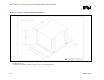
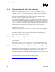
Requirement 2: The clip-bearing surface must meet the following specifications to ensure
adequate interface with the clip lever through its entire range of motion.
X and Y-dimensions: see Figure 21
Z-dimension: height of bearing surface above bottom surface of heatsink base
must be 1.817 ±0.007 inch
Clip bearing surface roughness must be as defined by SPI B-1 finish or better.
Requirement 3: Heatsink /shroud structural characteristics
Vertical load carrying capability: Each of the two clip bearing surfaces must be
capable of carrying 70 lb of load oriented in the z-direction. The sub-structure
(typically the heatsink) must be capable of receiving this load and transferring it
to the heatsink /package interface.
Lateral load carrying capability: The heatsink must be capable of carrying
100 lbs of load in both x and y-directions at the points of contact between the
heatsink base and RM.
Stiffness: The structure of the heatsink assembly must have a stiffness
equal to or greater than 30,000 lb/in along the z-axis to ensure
proper preload induced by the clips.
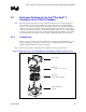
Requirement 4: Max mass and Center of Gravity (CG)
The combined mass of the reference heatsink/fan/shroud assembly is 370 g. The
mechanical reference components (retention mechanism and clip) have been
validated in mechanical shock and vibration according to the Intel validation
criteria defined section 3.1.3 with the reference heatsink. If a cooling solution