
Intel Pentium 4 Processor in the 478-PinPackage at 1.40 GHz, 1.50 GHz, 1.60 GHz, 1.70 GHz, 1.80 GHz, 1.90 GHz, and 2GHz

Electrical Specifications
Datasheet 15
.
NOTES:
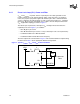
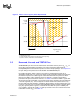
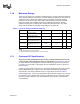
1. Diagram not to scale.
2. No specification for frequencies beyond fcore (core frequency).
3. fpeak, if existent, should be less than 0.05 MHz.
2.5 Reserved, Unused, and TESTHI Pins
All RESERVED pins must remain unconnected. Connection of these pins to V
CC
,V
SS
,or
to any other signal (including each other) can result in component malfunction or
incompatibility with a future Pentium 4 processor in the 478-pin package. See Chapter 5.0
for a pin listing of the processor and the location of all RESERVED pins.
For reliable operation, always connect unused inputs or bidirectional signals to an
appropriate signal level. In a system level design, on-die termination has been included on
the Pentium 4 processor to allow signals to be terminated within the processor silicon.
Most unused AGTL+ inputs should be left as no connects, as AGTL+ termination is
provided on the processor silicon. However, see Tab le 3 for details on AGTL+ signals that
do not include on-die termination. Unused active high inputs should be connected through
a resistor to ground (V
SS
). Unused outputs can be left unconnected, however this may
interfere with some TAP functions, complicate debug probing, and prevent boundary scan
testing. A resistor must be used when tying bidirectional signals to power or ground. When
tying any signal to power or ground, a resistor will also allow for system testability. For
unused AGTL+ input or I/O signals, use pull-up resistors of the same value for the on-die
termination resistors (R
TT
). See Ta b le 1 2.
Figure 2. Phase Lock Loop (PLL) Filter Requirements
0dB
-28 dB
-34 dB
0.2 dB
forbidden
zone
-0.5 dB
forbidden
zone
1MHz 66MHz
f
core
f
pea
k
1HzDC
passband
high frequency
band