
Intel Pentium 4 Processor in the 478-PinPackage at 1.40 GHz, 1.50 GHz, 1.60 GHz, 1.70 GHz, 1.80 GHz, 1.90 GHz, and 2GHz

Electrical Specifications
Datasheet 25
2.12 AGTL+ System Bus Specifications
Routing topology recommendations may be found in the appropriate Platform Design
Guide as referenced in Table 1. Termination resistors are not required for most AGTL+
signals, as these are integrated into the processor silicon.
Valid high and low levels are determined by the input buffers which compare a signal’s
voltage with a reference voltage called GTLREF (known as V
REF
in previous
documentation).
Table 12 lists the GTLREF specifications. The AGTL+ reference voltage (GTLREF) should
be generated on the system board using high precision voltage divider circuits. It is
important that the system board impedance is held to the specified tolerance, and that the
intrinsic trace capacitance for the AGTL+ signal group traces is known and well-controlled.
For more details on platform design see the Platform Design Guide.
NOTES:
1. Unless otherwise noted, all specifications in this table apply to all processor frequencies.
2. The tolerances for this specification have been stated generically to enable the system designer to calculate
the minimum and maximum values across the range of V
CC
.
3. GTLREF should be generated from V
CC
by a voltage divider of 1% resistors or 1% matched resistors. Refer
to Table 1 for the appropriate Platform Design Guide for implementation details.
4. R
TT
is the on-die termination resistance measured at V
OL
of the AGTL+ output driver. Refer to processor I/O
buffer models for I/V characteristics.
5. COMP resistance must be provided on the system board with 1% resistors. See the appropriate Platform
Design Guide for implementation details.
6. The V
CC
referred to in these specifications is the instantaneous V
CC
.
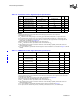
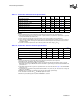
2.13 System Bus AC Specifications
The processor system bus timings specified in this section are defined at the
processor core silicon and are thus not measurable at the processor pins.See
Chapter 5.0 for the Pentium 4 processor in the 478-pin package pin signal definitions.
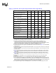
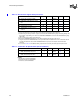
Table 13 through Ta b l e 1 8 list the AC specifications associated with the processor system
bus.
All AGTL+ timings are referenced to GTLREF for both ‘0’ and ‘1’ logic levels unless
otherwise specified.
The timings specified in this section should be used in conjunction with the I/O buffer
models provided by Intel. These I/O buffer models, which include package information,
are available for the Pentium 4 processor in the 478-pin package in IBIS format. AGTL+
layout guidelines are also available in the appropriate Platform Design Guide.
Care should be taken to read all notes associated with a particular timing parameter.
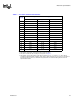
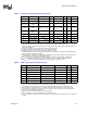
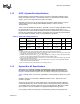
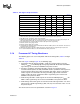
Table 12. AGTL+ Bus Voltage Definitions
Symbol Parameter Min Typ Max Units Notes
1
GTLREF
Bus Reference
Voltage
2/3 V
CC
-2% 2/3V
CC
2/3 V
CC
+ 2% V 2, 3, 6
R
TT
Termination
Resistance
45 50 55 Ω 4
COMP[1:0]
COMP
Resistance
50.49 51 51.51 Ω 5