
Intel Pentium 4 Processor in the 478-PinPackage at 1.40 GHz, 1.50 GHz, 1.60 GHz, 1.70 GHz, 1.80 GHz, 1.90 GHz, and 2GHz

System Bus Signal Quality Specifications
38 Datasheet
NOTES:
1. Unless otherwise noted, all specifications in this table apply to all Pentium® 4 processor in the 478-pin
package frequencies.
2. The rising and falling edge ringback voltage specified is the minimum (rising) or maximum (falling) absolute
voltage the BCLK signal can dip back to after passing the V
IH
(rising) or V
IL
(falling) voltage limits. This
specification is an absolute value.
3.2 System Bus Signal Quality Specifications and
Measurement Guidelines
Many scenarios have been simulated to generate a set of AGTL+ layout guidelines which
are available in the Platform Design Guide.
Tab l e 20 provides the signal quality specifications for all processor signals for use in
simulating signal quality at the processor silicon. In the future, the Pentium® 4 Processor
in the 478-pin Package Overshoot, Undershoot and Timing Validation Guidelines will be
available to assist in comparing specifications for signal quality at the processor silicon
with measurements taken at the processor pins.
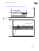
The Pentium® 4 processor in the 478-pin package maximum allowable overshoot and
undershoot specifications for a given duration of time are detailed in Ta bl e 2 2 through
Tab l e 25. Figure 17 shows the system bus ringback tolerance for low-to-high transitions
and Figure 18 shows ringback tolerance for high-to-low transitions.
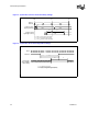
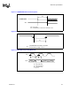
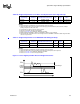
Table 19. BCLK Signal Quality Specifications
Parameter Min Max Unit Figure Notes
1
BCLK[1:0] Overshoot N/A 0.30 V 16
BCLK[1:0] Undershoot N/A 0.30 V 16
BCLK[1:0] Ringback Margin 0.20 N/A V 16
BCLK[1:0] Threshold Region N/A 0.20 V 16 2
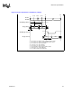
Figure 16. BCLK Signal Integrity Waveform
Crossing
Voltage
Threshold
Region
VH
VL
Overshoot
Undershoot
Ringback
Margin
Rising Edge
Ringback
Falling Edge
Ringback,
BCLK0
BCLK1
Crossing
Voltage