
Intel Pentium 4 Processor in the 478-PinPackage at 1.40 GHz, 1.50 GHz, 1.60 GHz, 1.70 GHz, 1.80 GHz, 1.90 GHz, and 2GHz

System Bus Signal Quality Specifications
Datasheet 41
3.3 System Bus Signal Quality Specifications and
Measurement Guidelines
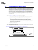
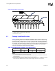
3.3.1 Overshoot/Undershoot Guidelines
Overshoot (or undershoot) is the absolute value of the maximum voltage above the
nominal high voltage (or below V
SS
)asshowninFigure 21. The overshoot/undershoot
guidelines limit transitions beyond V
CC
or V
SS
due to the fast signal edge rates. The
processor can be damaged by repeated overshoot or undershoot events on any input,
output, or I/O buffer if the charge is large enough (i.e., if the over/undershoot is great
enough). Determining the impact of an overshoot/undershoot condition requires
knowledge of the magnitude, the pulse direction, and the activity factor (AF) of the incident
waveform. Permanent damage to the processor is the likely result of excessive overshoot/
undershoot.
When performing simulations to determine impact of overshoot and undershoot, ESD
diodes must be properly characterized. ESD protection diodes do not act as voltage
clamps and will not provide overshoot or undershoot protection. ESD diodes modelled
within Intel I/O buffer models do not clamp undershoot or overshoot and will yield correct
simulation results. If other I/O buffer models are being used to characterize the Pentium 4
processor in the 478-pin package system bus, care must be taken to ensure that ESD
models do not clamp extreme voltage levels. Intel I/O buffer models also contain I/O
capacitance characterization. Therefore, removing the ESD diodes from an I/O buffer
model will impact results and may yield excessive overshoot/undershoot.
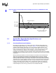
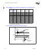
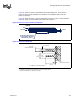
Figure 20. High-to-Low System Bus Receiver Ringback Tolerance for PWRGOOD and TAP
Buffers
0.5 * Vcc
Vt+ (min)
Vt- (max)
Vcc
Vss
Vt- (min)
ThresholdRegiontoswitch
receiver to a logic 0.
Allowable Ringback