
Intel Pentium 4 Processor in the 478-PinPackage at 1.40 GHz, 1.50 GHz, 1.60 GHz, 1.70 GHz, 1.80 GHz, 1.90 GHz, and 2GHz

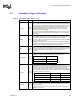

Pin Listing and Signal Definitions
70 Datasheet
BINIT#
Input/
Output
BINIT# (Bus Initialization) may be observed and driven by all processor system
bus agents and if used, must connect the appropriate pins of all such agents. If
the BINIT# driver is enabled during power-on configuration, BINIT# is asserted
to signal any bus condition that prevents reliable future operation.
If BINIT# observation is enabled during power-on configuration, and BINIT# is
sampled asserted, symmetric agents reset their bus LOCK# activity and bus
request arbitration state machines. The bus agents do not reset their IOQ and
transaction tracking state machines upon observation of BINIT# activation. Once
the BINIT# assertion has been observed, the bus agents will re-arbitrate for the
system bus and attempt completion of their bus queue and IOQ entries.
If BINIT# observation is disabled during power-on configuration, a central agent
may handle an assertion of BINIT# as appropriate to the error handling
architecture of the system.
BNR#
Input/
Output
BNR# (Block Next Request) is used to assert a bus stall by any bus agent who is
unable to accept new bus transactions. During a bus stall, the current bus owner
cannot issue any new transactions.
BPM[5:0]#
Input/
Output
BPM[5:0]# (Breakpoint Monitor) are breakpoint and performance monitor
signals. They are outputs from the processor which indicate the status of
breakpoints and programmable counters used for monitoring processor
performance. BPM[5:0]# should connect the appropriate pins of all Pentium 4
processor in the 478-pin package system bus agents.
BPM4# provides PRDY# (Probe Ready) functionality for the TAP port. PRDY# is
a processor output used by debug tools to determine processor debug
readiness.
BPM5# provides PREQ# (Probe Request) functionality for the TAP port. PREQ#
is used by debug tools to request debug operation of the processor.
Please refer to Table 1 for the appropriate Platform Design Guide, and the
ITP700 Debug Port Design Guide for more detailed information.
These signals do not have on-die termination. Refer to Section 2.5,andthe
appropriate Platform Design Guide for termination requirements.
BPRI# Input
BPRI# (Bus Priority Request) is used to arbitrate for ownership of the processor
system bus. It must connect the appropriate pins of all processor system bus
agents. Observing BPRI# active (as asserted by the priority agent) causes all
other agents to stop issuing new requests, unless such requests are part of an
ongoing locked operation. The priority agent keeps BPRI# asserted until all of its
requests are completed, then releases the bus by deasserting BPRI#.
BR0#
Input/
Output
BR0# drives the BREQ0# signal in the system and is used by the processor to
request the bus. During power-on configuration this pin is sampled to determine
the agent ID = 0.
This signal does not have on-die termination and must be terminated.
BSEL[1:0] Output
The BCLK[1:0] frequency select signals BSEL[1:0] are used to select the
processor input clock frequency. Table 4 defines the possible combinations of
the signals and the frequency associated with each combination. The required
frequency is determined by the processor, chipset and clock synthesizer. All
agents must operate at the same frequency. The Pentium 4 processor in the
478-pin package operates currently at a 400 MHz system bus frequency
(100 MHz BCLK[1:0] frequency). For more information about these pins,
including termination recommendations refer to Section 2.9 and the appropriate
Platform Design Guide.
COMP[1:0] Analog
COMP[1:0] must be terminated on the system board using precision resistors.
Refer to the appropriate Platform Design Guide for details on implementation.
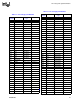
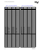
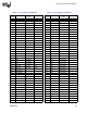
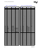
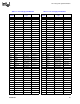
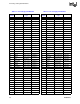
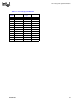
Table 32. Signal Description (Sheet 2 of 8)
Name Type Description