
Intel Pentium 4 Processor on 90 nm Process Thermal and Mechanical Design Guidelines

Mechanical Requirements
R
14 Intel
®
Pentium
®
4 on 90 nm Process Thermal Design Guide
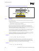
2.2 Heatsink Attach
There are no features on the mPGA478 socket to directly attach a heatsink: a mechanism must be
designed to support the heatsink. In addition to holding the heatsink in place on top of the IHS,
this mechanism plays a significant role in the robustness of the system in which it is implemented,
in particular:
• Ensuring thermal performance of the thermal interface material (TIM) applied between the
IHS and the heatsink. TIMs based on phase change materials are very sensitive to applied
pressure: the higher the pressure, the better the initial performance. TIMs such as thermal
greases are not as sensitive to applied pressure. Refer to Section 3.2.1.2 and Appendix A for
information on tradeoffs made with TIM selection. Designs should consider possible
decrease in applied pressure over time due to potential structural relaxation in retention
components.
• Ensuring system electrical, thermal, and structural integrity under shock and vibration events.
The mechanical requirements of the attach mechanism depend on the weight of the heatsink
and the level of shock and vibration that the system must support. The overall structural
design of the motherboard and the system has to be considered as well when designing the
heatsink attach mechanism. The design should provide a means for protecting mPGA478
socket solder joints as well as prevent package pullout from the socket.
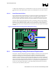
A popular mechanical solution for heatsink attach is the use of a retention mechanism and attach
clips. In this case, the clips should be designed to the general guidelines given above, in addition
to the following:
• Ability to hold the heatsink in place under mechanical shock and vibration events and apply
force to the heatsink base to maintain desired pressure on the thermal interface material. The
load applied by the clip also plays a role in ensuring that the package does not disengage
from the socket during mechanical shock. Note that the load applied by the clips must comply
with the package specifications described in Section 2.1, along with the dynamic load added
by the mechanical shock and vibration requirements.
• Engages easily with the retention mechanism tabs, and if possible, without the use of special
tools. In general, the heatsink and clip are assumed to be installed after the motherboard has
been installed into the chassis.
• Minimizes contact with the motherboard surface during clip attach to the retention
mechanism tab features; the clip should not scratch the motherboard.
The Intel reference design for the Pentium 4 processor in the 478-Pin Package (or Pentium 4
processor on 90 nm process ) is using a retention mechanism and clip assembly. Refer to
Chapter 4 and the document titled Mechanical Enabling for the Intel
®
Pentium
®
4 Processor in
the 478-Pin Package for further information regarding the Intel reference mechanical solution.