
Intel Pentium 4 Processor on 90 nm Process Thermal and Mechanical Design Guidelines

Thermal Requirements
R
Intel
®
Pentium
®
4 on 90 nm Process Thermal Design Guide 21
3.3 Thermal Metrology for the Intel
®
Pentium
®
4
Processor on 90 nm Process
3.3.1 Processor Heatsink Performance Assessment
This section discusses guidelines for testing thermal solutions, including measuring processor
temperatures. In all cases, the thermal engineer must measure power dissipation and temperature
to validate a thermal solution.
Thermal performance of a heatsink should be assessed using a thermal test vehicle (TTV)
provided by Intel. The TTV is a well-characterized thermal tool, whereas real processors can
introduce additional factors that can impact test results. In particular, the power level from actual
processors varies significantly due to variances in the manufacturing process. The TTV provides
consistent power and power density for thermal solution characterization and results can be easily
translated to real processor performance. Accurate measurement of the power dissipated by an
actual processor is beyond the scope of this document.
Once the thermal solution is designed and validated with the TTV, it is strongly recommended to
verify functionality of the thermal solution on real processors and on fully integrated systems (see
Section 3.4).
3.3.2 Local Ambient Temperature Measurement Guidelines
The local ambient temperature T
A
is the temperature of the ambient air surrounding the processor.
For a passive heatsink, T
A
is defined as the heatsink approach air temperature; for an actively
cooled heatsink, it is the temperature of inlet air to the active cooling fan.
It is worthwhile to determine the local ambient temperature in the chassis around the processor to
understand the effect it may have on the case temperature.
T
A
is best measured by averaging temperature measurements at multiple locations in the heatsink
inlet airflow. This method helps reduce error and eliminates minor spatial variations in
temperature. The following guidelines are meant to enable accurate determination of the localized
air temperature around the processor during system thermal testing.
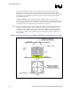
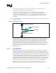
For active heatsinks, it is important to avoid taking measurement in the dead flow zone that
usually develops above the fan hub and hub spokes. Measurements should be taken at four
different locations uniformly placed at the center of the annulus formed by the fan hub and the fan
housing to evaluate the uniformity of the air temperature at the fan inlet. The thermocouples
should be placed approximately 3 mm to 8 mm [0.1 to 0.3 in] above the fan hub vertically and
halfway between the fan hub and the fan housing horizontally as shown in Figure 4 (avoiding the
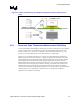
hub spokes). Using an open bench to characterize an active heatsink can be useful, and usually
ensures more uniform temperatures at the fan inlet. However, additional tests that include a solid
barrier above the test motherboard surface can help evaluate the potential impact of the chassis.
This barrier is typically clear Plexiglas*, extending at least 100 mm [4 in] in all directions beyond
the edge of the thermal solution. Typical distance from the motherboard to the barrier is 81 mm
[3.2 in]. For even more realistic airflow, the motherboard should be populated with significant
elements like memory cards, AGP card, and chipset heatsink. If a barrier is used, the
thermocouple can be taped directly to the barrier with a clear tape at the horizontal location as
previously described, half way between the fan hub and the fan housing. If a variable speed fan is