
Intel Pentium 4 Processor on 90 nm Process Thermal and Mechanical Design Guidelines

Thermal Requirements
R
22 Intel
®
Pentium
®
4 on 90 nm Process Thermal Design Guide
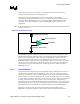
used, it may be useful to add a thermocouple taped to the barrier above the location of the
temperature sensor used by the fan to check its speed setting against air temperature. When
measuring T
A
in a chassis with a live motherboard, add-in cards, and other system components, it
is likely that the T
A
measurements will reveal a highly non-uniform temperature distribution
across the inlet fan section.
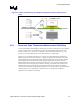
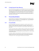
For passive heatsinks, thermocouples should be placed approximately 13 mm to 25 mm
[0.5 to 1.0 in] away from processor and heatsink as shown in Figure 4. The thermocouples should
be placed approximately 51 mm [2.0 in] above the baseboard. This placement guideline is meant
to minimize the effect of localized hot spots from baseboard components.
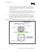
Note: Testing active heatsink with a variable speed fan can be done in a thermal chamber to capture the
worst-case thermal environment scenarios. Otherwise, when doing a bench top test at room
temperature, the fan regulation prevents the heatsink from operating at its maximum capability.
To characterize the heatsink capability in the worst-case environment in these conditions, it is
then necessary to disable the fan regulation and power the fan directly, based on guidance from
the fan supplier.
Figure 4. Locations for Measuring Local Ambient Temperature, Active Heatsink (not to scale)