
Intel Pentium 4 Processor on 90 nm Process Thermal and Mechanical Design Guidelines

Thermal Requirements
R
24 Intel
®
Pentium
®
4 on 90 nm Process Thermal Design Guide
3.4 Thermal Management Logic and Thermal Monitor
Feature
3.4.1 Processor Power Dissipation
An increase in processor operating frequency not only increases system performance, but also
increases the processor power dissipation. The relationship between frequency and power is
generalized in the following equation:
P = CV
2
F (where P = power, C = capacitance, V = voltage, F = frequency).
From this equation, it is evident that power increases linearly with frequency and with the square
of voltage. In the absence of power saving technologies, increasing frequencies will result in
processors with power dissipations in the hundreds of Watts. Fortunately, there are numerous
ways to reduce the power consumption of a processor, and Intel is aggressively pursuing low
power design techniques. For example, decreasing the operating voltage, reducing unnecessary
transistor activity, and using more power efficient circuits can significantly reduce processor
power consumption.
An on-die thermal management feature called Thermal Monitor is available on the Pentium 4
processor on 90 nm process. It provides a thermal management approach to support the continued
increases in processor frequency and performance. By using a highly accurate on-die temperature
sensing circuit and a fast acting temperature control circuit (TCC), the processor can rapidly
initiate thermal management control. The Thermal Monitor can reduce cooling solution cost, by
allowing designs to target the thermal design power (TDP) instead of maximum power, without
impacting processor reliability or performance.
3.4.2 Thermal Monitor Implementation
On the Pentium 4 processor on 90 nm process, the Thermal Monitor is integrated into the
processor silicon. The Thermal Monitor includes:
• A highly accurate on-die temperature sensing circuit
• A bi-directional signal (PROCHOT#) that indicates either the processor has reached its
maximum operating temperature or can be asserted externally to activate the thermal control
circuit (TCC) (see Section 3.4.3 for more details on user activation of TCC via PROCHOT#).
• A thermal control circuit that can reduce processor temperature by rapidly reducing power
consumption when the on-die temperature sensor indicates that it has reached the maximum
operating point.
• Registers to determine the processor thermal status.
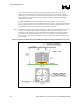
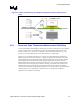
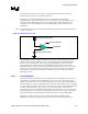
The processor temperature is determined through an analog thermal sensor circuit comprised of a
temperature sensing diode, a factory calibrated reference current source, and a current comparator
(See Figure 6). A voltage applied across the diode induces a current flow that varies with
temperature. By comparing this current with the reference current, the processor temperature can