
Intel Pentium 4 Processor on 90 nm Process Thermal and Mechanical Design Guidelines

Thermal Requirements
R
Intel
®
Pentium
®
4 on 90 nm Process Thermal Design Guide 25
be determined. The reference current source corresponds to the diode current when at the
maximum permissible processor operating temperature.
The temperature at which PROCHOT# goes active is individually calibrated during
manufacturing. The power dissipation of each processor affects the set point temperature. The
temperature where PROCHOT# goes active is roughly parallel to the thermal profile. Once
configured, the processor temperature at which the PROCHOT# signal is asserted is not re-
configurable.
Note: A thermal solution designed to meet the thermal profile and TDP targets should rarely experience
activation of the TCC.
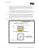
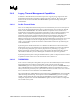
Figure 6. Thermal Sensor Circuit
PROCHOT#
Temperature sensing diode
Reference current source
Current comparator
The PROCHOT# signal is available internally to the processor as well as externally. External
indication of the processor temperature status is provided through the bus signal PROCHOT#.
When the processor temperature reaches the trip point, PROCHOT# is asserted. When the
processor temperature is below the trip point, PROCHOT# is de-asserted. Assertion of the
PROCHOT# signal is independent of any register settings within the processor. It is asserted any
time the processor die temperature reaches the trip point. The point where the thermal control
circuit activates is set to the same temperature at which the processor is tested and at which
PROCHOT# asserts.
3.4.2.1 Thermal Monitor
The thermal control circuit portion of the Thermal Monitor must be enabled for the processor to
operate within specifications. The Thermal Monitor’s TCC, when active, lowers the processor
temperature by reducing the power consumed by the processor. In the original implementation of
thermal monitor, this is done by changing the duty cycle of the internal processor clocks, resulting
in a lower effective frequency. When active, the TCC turns the processor clocks off and then back
on with a predetermined duty cycle. The duty cycle is processor specific, and is fixed for a
particular processor. The maximum time period the clocks are disabled is ~3 µs, and is frequency
dependent. Higher frequency processors will disable the internal clocks for a shorter time period.
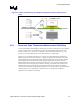
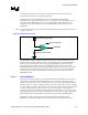
Figure 7 illustrates the relationship between the internal processor clocks and PROCHOT#.
Performance counter registers, status bits in model specific registers (MSRs), and the
PROCHOT# output pin are available to monitor and control the Thermal Monitor behavior.