
Intel Pentium 4 Processor on 90 nm Process Thermal and Mechanical Design Guidelines

Thermal Requirements
R
Intel
®
Pentium
®
4 on 90 nm Process Thermal Design Guide 27
enabled, processor power consumption will be reduced within a few hundred clock cycles after
the thermal sensor detects a high temperature (i.e., PROCHOT# assertion). The thermal control
circuit and PROCHOT# transition to inactive once the temperature has been reduced below the
thermal trip point, although a small time-based hysteresis has been included to prevent multiple
PROCHOT# transitions around the trip point. External hardware can monitor PROCHOT# and
generate an interrupt when there is a transition from active-to-inactive or inactive-to-active.
PROCHOT# can also be configured to generate an internal interrupt that would initiate an OEM
supplied interrupt service routine. Regardless of the configuration selected, PROCHOT# will
always indicate the thermal status of the processor.
The power reduction mechanism of thermal monitor can also be activated manually using an “on-
demand” mode. Refer to Section 3.4.5 for details on this feature.
3.4.5 On-Demand Mode
For testing purposes, the thermal control circuit may also be activated by setting bits in the ACPI
MSRs. The MSRs may be set based on a particular system event (e.g., an interrupt generated after
a system event), or may be set at any time through the operating system or custom driver control
thus forcing the thermal control circuit on. This is referred to as “on-demand” mode. Activating
the thermal control circuit may be useful for thermal solution investigations or for performance
implication studies. When using the MSRs to activate the Thermal Monitor feature, the duty cycle
is configurable in steps of 12.5%, from 12.5% to 87.5%.
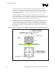
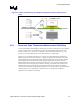
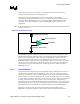
For any duty cycle, the maximum time period the clocks are disabled is ~3 µs. This time period is
frequency dependent, and decreases as frequency increases. To achieve different duty cycles, the
length of time that the clocks are disabled remains constant, and the time period that the clocks
are enabled is adjusted to achieve the desired ratio. For example, if the clock disable period is
3 µs, and a duty cycle of ¼ (25%) is selected, the clock on time would be reduced to
approximately 1 µs [on time (1 µs) ÷ total cycle time (3 + 1) µs = ¼ duty cycle]. Similarly, for a
duty cycle of 7/8 (87.5%), the clock on time would be extended to 21 µs [21 ÷ (21 + 3) = 7/8 duty
cycle].
In a high temperature situation, if the thermal control circuit and ACPI MSRs (automatic and on-
demand modes) are used simultaneously, the fixed duty cycle determined by automatic mode
would take precedence.