
Intel Pentium 4 Processor on 90 nm Process Thermal and Mechanical Design Guidelines

Thermal Requirements
R
30 Intel
®
Pentium
®
4 on 90 nm Process Thermal Design Guide
3.4.9 Cooling System Failure Warning
If desired, the system may be designed to cool the maximum processor power. In this situation, it
may be useful to use the PROCHOT# signal as an indication of cooling system failure. Messages
could be sent to the system administrator to warn of the cooling failure, while the thermal control
circuit would allow the system to continue functioning or allow a normal system shutdown. If no
thermal management action is taken, the silicon temperature may exceed the operating limits,
causing THERMTRIP# to activate and shut down the processor. Regardless of the system design
requirements or thermal solution ability, the Thermal Monitor feature must still be enabled to
ensure proper processor operation.
3.5 Thermal Specification
Intel has introduced a new method for specifying the thermal limits for the Pentium 4 processor
on 90 nm process. The new parameters are the Thermal Profile and T
CONTROL
. The Thermal Profile
defines the maximum case temperature. T
CONTROL
is a specification used in conjunction with the
temperature reported by the on-die thermal diode.
3.5.1 Thermal Profile
The thermal profile defines the maximum case temperature as a function of processor power
dissipation. The TDP and maximum case temperature for loadline A of the Pentium 4 processor
on 90 nm process are defined as the maximum values of the thermal profile. By design the
thermal solutions must meet the thermal profile for all system operating conditions and processor
power levels.
The slope of the thermal profile was established assuming a generational improvement in thermal
solution performance of about 10% based on previous Intel reference designs. This performance
is expressed as the slope on the thermal profile and can be thought of as the ΨCA. The intercept
on the thermal profile assumes a maximum ambient operating condition that is consistent with the
available chassis solutions.
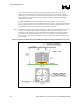
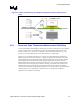
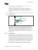
To determine compliance to the thermal profile, a measurement of the actual processor power
dissipated is required. The measured power is plotted on the thermal profile to determine the
maximum case temperature. Using the example in Figure 8 a power dissipation of 70 W has a
case temperature of 61°C. See the appropriate datasheet for the thermal profile.