
Intel Pentium 4 Processor on 90 nm Process Thermal and Mechanical Design Guidelines

Thermal Requirements
R
Intel
®
Pentium
®
4 on 90 nm Process Thermal Design Guide 33
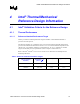
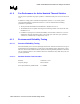
3.6.1 Example Implementation
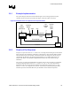
The system designer must work with the board designer to select the appropriate fan speed
controller. For processor fan speed control the Figure 9 shows the major connections.
Figure 9. Example Acoustic Fan Speed Control Implementation
HS Fan
Processor
Fan Speed
Controller
PWM
Tachometer
Thermal Diode
(2 wires)
+12V
GND
Sys
Ambient
(Opt)
Sys Fan
4wire
PWM
(2x)
T control
BIOS
Inlet
Ambient
(Thermistor)
4-Pin Fan
Header
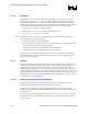
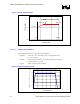
3.6.2 Graphs of Fan Response
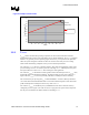
In Figure 10 a processor with a T
CONTROL
value of 70 °C is being measured using the on-die thermal
diode. The fan in this example has a thermistor on the fan hub, as does the Intel enabled solution
and the Intel boxed processor heatsink. This thermal solution was designed so the fan speed, as
controlled by the thermistor, will meet the thermal profile at every ambient temperature. See
Chapter 4 for details on the thermistor implementation and the rest of the reference design
information.
The processor is running the 3Dmark2001* benchmark. The fan speed controller is programmed
to begin accelerating the fan speed at T
CONTROL
minus 5 °C or 65 °C. As a result, the processor
heatsink fan will not accelerate from the minimum programmed fan speed for any T
diode
value
below 65 °C. Once T
diode
temperature exceeds 65 °C, the fan speed will ramp linearly from the
minimum speed to the maximum allowed by the thermistor for that ambient temperature.