
Intel Pentium 4 Processor on 90 nm Process Thermal and Mechanical Design Guidelines

Thermal Requirements
R
34 Intel
®
Pentium
®
4 on 90 nm Process Thermal Design Guide
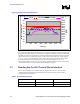
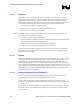
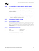
Figure 10. Example Fan Speed Response
40
45
50
55
60
65
70
75
80
0 100 200 300 400 500 600 700
Time (s)
Diode temperature (C)
0
500
1000
1500
2000
2500
3000
3500
4000
4500
5000
5500
6000
RPM
Tdiode Templow Temphigh RPM
The choice of accelerating the fan speed over a 5 °C range is an aggressive acoustic solution. For
the typical home/office ambient environment and workloads, the fan will remain at the minimum
operating speed for most workloads. Once the lower temperature threshold is reached, fan speed
change can be rapid. An alternate approach is to have the fan speed ramp over a larger range of
T
diode
(e.g., 10 °C). This will reduce the rate of change for the fan speed, but may raise acoustic
level more often at the low ambient condition as the fan response begins at lower T
diode
temperatures. In either case, the use of a “smoothing” parameter options in the fan speed control
chip is recommended to average out short duration temperature spikes.
3.7 Reading the On-Die Thermal Diode Interface
The on-die thermal diode is accessible from a pair of pins on the processor. The fan speed
controller remote thermal sense signals should be connected to these pins per the vendor’s
recommended layout guidelines.
Table 1. Thermal Diode Interface
Pin Name Pin Number Pin Description
THERMDA
B3 Diode anode
THERMDC
C4 Diode anode