
Intel Pentium 4 Processor on 90 nm Process Thermal and Mechanical Design Guidelines

Intel® Thermal/Mechanical Reference Design Information
R
Intel
®
Pentium
®
4 on 90 nm Process Thermal Design Guide 43
4.1.5 Safety Requirements
Heatsink and attachment assemblies shall be consistent with the manufacture of units that meet
the safety standards:
• UL Recognition-approved for flammability at the system level. All mechanical and thermal
enabling components must be a minimum UL94V-2 approved.
• CSA Certification. All mechanical and thermal enabling components must have CSA
certification.
• Heatsink fins must meet the test requirements of UL1439 for sharp edges.
• If the International Accessibility Probe specified in IEC 950 can access the moving parts of
the fan, consider adding safety feature so that there is no risk of personal injury to one’s
finger.
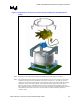
4.1.6 Geometric Envelope for Intel Reference Thermal
Mechanical Design
Figure 26, Figure 27, and Figure 28 in Appendix C show the overall keep-out and keep-in
dimensions for the reference thermal/mechanical enabling design. These dimensions are identical
to the ones used for the Intel reference design for the Pentium 4 processor in the 478-pin package
and the Pentium 4 processor with 512-KB L2 cache on 0.13 micron process.
Figure 26 and Figure 27 show the motherboard keep-outs and height restrictions under the
enabling component region. Figure 28 shows the overall volumetric keep-in for the enabling
component assembly. This volumetric space encapsulates the processor, the socket, and the entire
thermal/mechanical enabling solution (for example, for the reference design this includes: fan
heatsink assembly, retention mechanism, and attach clips).
Note: Pin A1 and Ball A1, as referred to in Figure 26, do not physically exist on the 478-pin package
and the 478-pin socket respectively. However, they may be used as a reference for design
purposes. Motherboard designers should focus exclusively on Ball A1 callouts to determine
position of the hole respective to the socket when working of the board layout. By design, the
processor is then centered within the hole pattern when the socket is in the closed position. Pin A1
is associated specifically with the package, and its position on the drawing Figure 26 corresponds
to the package within the socket in close position.