
Intel Pentium 4 Processor on 90 nm Process Thermal and Mechanical Design Guidelines

Intel® Thermal/Mechanical Reference Design Information
R
46 Intel
®
Pentium
®
4 on 90 nm Process Thermal Design Guide
4.2.2 Reference Mechanical Components
4.2.2.1 Heatsink Attach Clip
The heatsink attach clip for the Pentium 4 processor on 90 nm process reference heatsink consists
of a one-piece plastic clip (LEXAN* 500ECR) identical to that used for the Pentium 4 processor
with 512-KB L2 cache on 0.13 micron process reference heatsink. A drawing of the clip is
provided in Appendix C.
4.2.2.2 Retention Mechanism
The retention mechanism for the Pentium 4 processor on 90 nm process thermal mechanical
reference solution is identical to the Pentium
4 processor in the 478-pin package reference
retention mechanism. A drawing of the retention mechanism is shown in Appendix C.
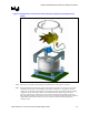
4.2.2.3 Heatsink
The heatsink consists of 62 extruded aluminum radial fins with an inserted copper core. The fins
are bent to direct airflow towards the center of the heatsink core and increase thermal
performance. A drawing of the heatsink is shown in Appendix C.
4.2.2.4 Thermal Interface Material
Refer to Section 3.2.1.2 for general information on thermal interface material usage and
application consideration on the FC-mPGA4 package.
Thermal interface material for the Intel reference design for the for the Pentium 4 processor on 90
nm process is Shin-etsu* G751 thermally conductive grease.
4.2.2.5 Fan and Hub Assembly
The fan impeller uses eight (8) blades optimized for the reference heatsink design. When used in
conjunction with the reference heatsink, a high level of cooling performance is achieved. The fan
motor resides in the fan hub, and is attached to the heatsink directly through a fan attach
component, avoiding the need for a fan shroud. A sketch of the impeller geometry is available in
Appendix C.
The reference fan may experience a startup current draw of 1.5 A for ~ 1 sec duration. This
exceeds the maximum steady state current draw of 740 mA stated in Section 4.1.2. Motherboard
designers should ensure the fan header can provide this transient current.
4.2.2.6 Fan Attach
The fan and hub assembly is attached to the heatsink assembly through a fan attach component.
The plastic fan attach component connects to the fan hub through four (4) tabs and is held in the
heatsink core area through barbs molded into the part. The fan attach component is pressed into
the heatsink through special tooling. Refer to Appendix C for a drawing of the component.