
Intel Pentium 4 Processor on 90 nm Process Thermal and Mechanical Design Guidelines

Appendix C: Mechanical Drawings
R
Intel
®
Pentium
®
4 on 90 nm Process Thermal Design Guide 53
Appendix C: Mechanical Drawings
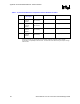
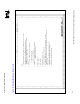
The following table lists the mechanical drawings included in this appendix. These drawings refer
to the thermal mechanical enabling components for the Pentium 4 processor on 90 nm process.
Note: Intel reserves the right to make changes and modifications to the design as necessary.
Drawing Description Page Number
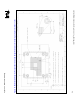
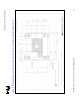
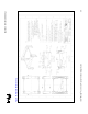
Motherboard Keep-Out Footprint Definition and Height Restrictions for Enabling
Components (Sheet 1 of 3)
54
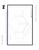
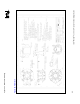
Motherboard Keep-out Footprint Definition and Height Restrictions for Enabling
Components (Sheet 2 of 3)
55
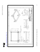
Motherboard Keep-out Footprint Definition and Height Restrictions for Enabling
Components (Sheet 3 of 3)
56
Retention Mechanism (Sheet 1 of 2) 57
Retention Mechanism (Sheet 2 of 2) 58
Heatsink Retention Clip 59
Fan Attach 60
Fan Impeller Sketch 61
Heatsink (Sheet 1 of 2) 62
Heatsink (Sheet 2 of 2) 63
Heatsink Assembly (Non-validated Fan Guard Shown. Sheet 1 of 2) 64
Heatsink Assembly (Non-validated fan guard shown, Sheet 2 of 2) 65