
Intel Pentium 4 Processor on 90 nm Process Thermal and Mechanical Design Guidelines

Appendix D: TCASE Reference Metrology
R
Intel
®
Pentium
®
4 on 90 nm Process Thermal Design Guide 69
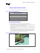
Thermocouple Attach Procedure
The following items are required for thermocouple removal or reattach.
Table 8. Thermalcouple Attach Material List
Thermalcouple Attach Material List
Scribe
Fine point tweezers
Exacto* knife (#11 blade)
Thermocouple (36 gauge, 0.9 m [36 in], Teflon insulation)
3M Kapton* tape cut into strips (3 mm x 13 mm [0.125 in x 0.5 in])
Epoxy (Omega Bond* 101)
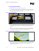
Thermocouple Preparation
The thermocouple wire must be prepared for attach using the following procedure.
1. Hold the thermocouple (T/C) in hand, locate the beaded end and straighten the wire by hand
so that the first 100–150 mm [4-6 in] are reasonably straight.
2. Use fine point tweezers to make sure that the bead and the two wires coming out are straight
and untwisted. Make sure that the second layer of insulation, which is sometimes clear, is not
covering the bead.
3. Bend both the thermocouple wires slightly at a location approximately 3 mm [0.125 in] away
from the thermocouple bead. When this thermocouple is placed on a flat surface the bend
serves to spring load the bead and guarantee that the thermocouple bead is making contact
with the bottom of the groove when it is inserted into the channel.
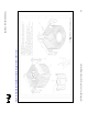
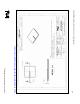
Figure 27. Thermocouple Wire Preparation