
Intel Pentium 4 Processor on 90 nm Process Thermal and Mechanical Design Guidelines
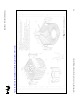


Appendix D: TCASE Reference Metrology
R
70 Intel
®
Pentium
®
4 on 90 nm Process Thermal Design Guide
Thermocouple Positioning
Position the thermocouple on the part using the following process.
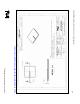
1) The TTV surface must be thoroughly cleaned in order to ensure a strong bond between the
epoxy and the surface of the part to which the thermocouple is being attached. Clean the TTV
surface with alcohol using a lint-free wipe or swab.
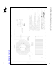
Figure 28. TTV Cleaning Preparation
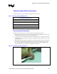
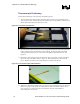
2) Place the thermocouple into the groove of the integrated heat spreader of the TTV so that the
bead is pointing down at the end of the grooved channel. The thermocouple bead should
extend past the end of the groove (at the center of the IHS) by approximately 4 mm. See
Figure 29.
3) Hold the T/C with one hand and use the tweezers to place a previously cut piece of Kapton*
tape on the edge of the IHS as shown in Figure 29. This will hold the wire down into the
groove. Rub the tape to allow for a good bond between the tape and the TTV.
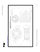
Figure 29. TTV Thermocouple Instrumentation
4) With the T/C temporarily attached to the part, mix the epoxy and prepare it for use. If Omega
Bond* 101 epoxy is used, squeeze out equal quantities of the resin and the catalyst onto a
piece of paper. Use a stirrer to mix the two ingredients. The end result should be a
consistently white viscous paste.