
Intel Pentium 4 Processor on 90 nm Process Thermal and Mechanical Design Guidelines

Appendix D: TCASE Reference Metrology
R
Intel
®
Pentium
®
4 on 90 nm Process Thermal Design Guide 71
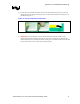
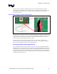
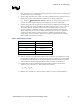
5) Lift the wire at the middle of channel with tweezers and bend the front of wire to place the
thermocouple in the channel ensuring the tip is in contact at the bottom end of the groove of
the IHS. See Figure 30.
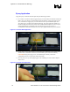
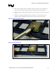
Figure 30. Thermocouple Attach Preparation
6)
I
I
m
m
p
p
o
o
r
r
t
t
a
a
n
n
t
t
!
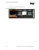
! Using an ohmmeter, measure the thermocouple electrical resistance. The
thermocouple resistance should be 25 Ω or less. If there is no continuity, it means that the
thermocouple bead is not touching the bottom of the grooved channel and that test results will
be inaccurate. If this occurs, start re-attach procedure again.