
Intel Pentium 4 Processor on 90 nm Process Thermal and Mechanical Design Guidelines

Appendix E: TTV Metrology
R
Intel
®
Pentium
®
4 on 90 nm Process Thermal Design Guide 77
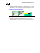
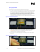
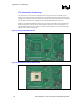
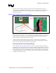
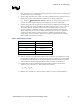
The heater can be accessed by soldering wires to the power and ground sides of one of the
capacitor pads. This establishes connections between the power supply and power/ground planes
on the motherboard. Since the heater is a simple resistor, the polarity of the power supply
connection is arbitrary.
Figure 39. Power Supply Connection to Motherboard
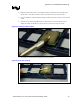
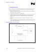
Measure the resistance between the power and ground planes with the socket empty to make sure
that the planes are separated (i.e., open circuit). With some Digital Multi-Meters, a measurement
of “O.L” will be seen. If a resistance is measured, the planes are short-circuited. Correct the
situation and achieve isolated planes before proceeding.
Insert a TTV into the socket and measure the resistance. A value of 23 Ω ± 3 Ω should be
measured. If the resistance deviates significantly, there may exist a wiring problem, a damaged
TTV, and/or a short-circuit between power and ground planes.
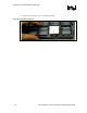
Recommended DC Power Supply Ratings
The recommended DC power supply rating is 120 V and 4 A. The power dissipation should be
maintained below 110 W and the TTV case temperature should be maintained below 80°C during
thermal testing. By violating the constraints, the TTV operational life will be reduced and/or the
unit may fail to function. Note that the reliability of TTV is limited and the TTV is not designed
for long-term testing purposes. The TTV should not be powered on without an attached heatsink
or damage to the TTV could occur.