
Intel Pentium 4 Processor on 90 nm Process Thermal and Mechanical Design Guidelines

Appendix E: TTV Metrology
R
78 Intel
®
Pentium
®
4 on 90 nm Process Thermal Design Guide
Thermal Measurements
Refer to Section 3.3.2 for T
A
measurement methodology. Refer to Appendix D for thermocouple
attachment to the HIS. Use the following instructions for performing thermal characterization
parameter measurements using the TTV:
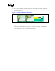
1. Attach a thermocouple at the center of the package (IHS-side) using the proper thermocouple
attach procedure (refer to Appendix D).
2. Connect the thermocouple to a meter or data logger.
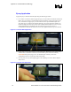
3. Apply thermal interface materials to either IHS top surface or on the surface of heatsink base.
4. Mount the heatsink to the TTV with the intended heatsink attach clip and all relevant
mechanical interface components (e.g., retention mechanism, processor EMI attenuation
solutions, etc.).
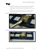
5. Place the TTV in the test environment (e.g., a test bench, a wind tunnel or a computer
chassis).
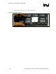
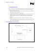
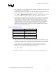
6. Connect the heater resistor of TTV to a DC power supply. Connect shunt resistor and voltage
meters as shown in Figure 40. Use a shunt resistor with a 0.01 Ω resistance so that the power
draw of the TTV will be unaffected.
Figure 40. Electrical Connection for Heater