
Intel Pentium 4 Processor VR-Down Design Guidelines
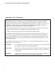
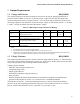
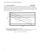
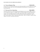
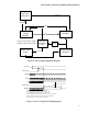
Table Of Contents
- Output Requirements
- Voltage and Current REQUIRED
- Voltage Tolerance REQUIRED
- Load Line Definitions REQUIRED
- Processor Electrical And Thermal Current Support EXPECTED
- No-Load Operation EXPECTED
- Turn-on Response Time PROPOSED
- Processor Power Sequencing REQUIRED
- Overshoot at Turn-On or Turn-Off REQUIRED
- Converter Stability REQUIRED
- Thermal Monitoring PROPOSED
- Input Voltage and Current
- Control Inputs REQUIRED
- Power Good Output (PWRGD) PROPOSED
- Efficiency PROPOSED
- Fault Protection
Intel
®
Pentium
®
4 Processor VR-Down Design Guidelines
10
Note: VID_GOOD is not a processor signal. This signal is routed to the
output enable pin of the voltage regluator control silicon.
1. This timing diagram is not intended to show specific times. Instead a
general ordering of events with respect to time should be observed.
2. When VCCVID is less than 1V, VID_GOOD must be low.
3. Vcc must be disabled before VID[4:0] becomes invalid.
Vcc
PWRGOOD
VCCVID
VID_GOOD
VID[4:0]
Figure 4: Power-off Sequence Timing Diagram
1.8 Overshoot at Turn-On or Turn-Off REQUIRED
Overshoot upon the application or removal of the input voltage must be such that Vcc does not exceed
the limits specified in Section 1.3. No negative voltage may be present on any output during turn-on or
turn-off.
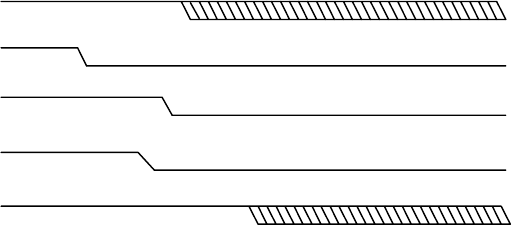
1.9 Converter Stability REQUIRED
The VR needs to be unconditionally stable under all output voltage ranges and current transients.
Stability requirements include a Thermal Monitor operating condition in which the processor may
periodically stop to reduce its power dissipation in response to a high-temperature alert. Figure 5 shows
worst-case Thermal Monitor operation (maximum current in the ON state).