
Intel Pentium 4 Processor VR-Down Design Guidelines
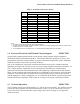
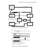
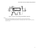
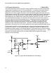
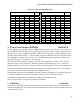
Table Of Contents
- Output Requirements
- Voltage and Current REQUIRED
- Voltage Tolerance REQUIRED
- Load Line Definitions REQUIRED
- Processor Electrical And Thermal Current Support EXPECTED
- No-Load Operation EXPECTED
- Turn-on Response Time PROPOSED
- Processor Power Sequencing REQUIRED
- Overshoot at Turn-On or Turn-Off REQUIRED
- Converter Stability REQUIRED
- Thermal Monitoring PROPOSED
- Input Voltage and Current
- Control Inputs REQUIRED
- Power Good Output (PWRGD) PROPOSED
- Efficiency PROPOSED
- Fault Protection
Intel
®
Pentium
®
4 Processor VR-Down Design Guidelines
12
1.10 Thermal Monitoring PROPOSED
This section describes how to protect the voltage regulator design from heat damage while
supporting thermal design current (TDC) specifications. It is included for reference and is
applicable to Intel® Pentium® 4 processors supporting Hyper-Threading Technology
1
operating at 3.06 GHz or higher. Intel does not recommend integrating this feature into Vcc
PWM controller designs. Each customer is responsible for identifying maximum temperature
specifications for all components in the voltage regulator design and ensuring that these
specifications are not violated while continuously drawing specified TDC levels. In the event
of a catastrophic thermal failure, the thermal monitoring circuit is to assert the Pentium 4
processor signal PROCHOT# immediately prior to exceeding maximum motherboard and
component thermal ratings to prevent heat damage. Assertion of this signal will lower
processor power consumption and reduce current draw through the voltage regulator,
resulting in lower component temperatures. Assertion of PROCHOT# degrades system
performance and must never occur when drawing less than specified thermal design current.
VR temperature violations can be detected using a thermal sensor and associated control
circuitry (see Figure 6). For this implementation, a thermistor (THMSTR) is placed in the
temperature sensitive region of the voltage regulator. The location must be chosen carefully
and is to represent the position where initial thermal violations are expected to occur. When
exceeded, the thermal monitor circuit is to initiate PROCHOT# to protect the voltage
regulator from heat damage.
0.1uF
3904
LM393
Vcc
6.8k
THMSTR
7.5kΩ
+
-
1kΩ
R2
499Ω
130Ω
R1
1kΩ
680Ω
R
PU
130Ω
Vcc
Vccp
PROCHOT#
Figure 6: Typical VR Thermal Monitor Circuit Design