
Intel Pentium 4 Processor VR-Down Design Guidelines
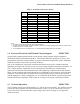
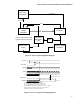
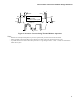
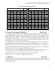
Table Of Contents
- Output Requirements
- Voltage and Current REQUIRED
- Voltage Tolerance REQUIRED
- Load Line Definitions REQUIRED
- Processor Electrical And Thermal Current Support EXPECTED
- No-Load Operation EXPECTED
- Turn-on Response Time PROPOSED
- Processor Power Sequencing REQUIRED
- Overshoot at Turn-On or Turn-Off REQUIRED
- Converter Stability REQUIRED
- Thermal Monitoring PROPOSED
- Input Voltage and Current
- Control Inputs REQUIRED
- Power Good Output (PWRGD) PROPOSED
- Efficiency PROPOSED
- Fault Protection

Intel
®
Pentium
®
4 Processor VR-Down Design Guidelines
13
Assertion of PROCHOT# is governed by the comparator (LM393) using the sensor voltage
(at the negative comparator terminal) and a trigger reference voltage (at the positive
comparator terminal). As the thermistor temperature increases due to system loading, the
resistance will decrease. When the voltage drop across the thermistor falls below the trigger
reference voltage, established by R1 and R2, the comparator will change state and bias the
bipolar transistor (BJT). When biased, the BJT provides the active low signal assertion of
PROCHOT# compliant to signaling specifications (see
Table 3).
Table 3, Thermal Monitor Specifications
Parameter
Specification
Minimum Maximum
Units
Termination voltage
†
(Vcc)
Volts
Output on (low) resistance
11 Ohms
Output leakage current
200 Microamperes
Transition time
0.550 100 Nanoseconds
Time in or out of Thermal
Monitor state
1.0
Milliseconds
R
PU
(Pull-up Resistor)
†
130Ω +/- 5%
Ohms
†
The thermal monitor circuit is to use a single motherboard pull up resistor to bias
the BJT collector. This is provided in the PROCHOT# circuit design. Additional
termination must not be integrated into the thermal monitoring circuit.
PROCHOT# is an open-drain, active-low i/o buffer terminated to the system Vtt (FSB
termination voltage). To maintain reliable signaling between thermal monitor circuit,
processor, and chipset, the bipolar transistor must be selected to operate with a collector
bias established using a single 130Ω
ΩΩ
Ω pull-up resistor. Use of additional termination or pull-up
resistors may lead to signal integrity or logic threshold failures.
The values for R1 and R2 in Figure 6 are included as an example and must be calculated
using specific design parameters. The value of R2 is adjusted to calibrate the comparator’s
trigger reference voltage (and assertion of PROCHOT#) against the sensor voltage
representing a thermal violation
.