
Intel Pentium 4 Processor with 512-KB L2 Cache on 0.13 Micron Process Thermal Design Guidelines


Mechanical Requirements
R
12 Intel
®
Pentium
®
4 Processor Thermal Design Guide
2.1.2 Heatsink Attach
There are no features on the mPGA478 socket to directly attach a heatsink. Therefore, a
mechanism must be designed to support the heatsink. In addition to holding the heatsink into place
on top of the IHS, this mechanism plays a significant role in the robustness of the system in which
it is implemented. In particular:
• Ensuring thermal performance of the thermal interface material used between the IHS and the
heatsink. Some of these materials are very sensitive to pressure applied to them; the higher the
pressure, the better the performance up to a point of diminishing return.
• Ensuring system electrical, thermal and structural integrity under shock and vibration events.
The mechanical requirements of the attach mechanism depend on the mass of the heatsink and
the level of shock and vibration that the system has to support. The overall structural design of
the motherboard and the system has to be considered as well when designing the heatsink
attach mechanism, in particular their impact on motherboard stiffening needed to protect
mPGA478 socket solder joint, and prevent package pull-out from the socket.
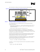
A popular solution for heatsink attach mechanism is to use a retention mechanism and attach clips.
In that case, the clips should be designed to the general guidelines given above. More particularly:
• To hold the heatsink in place under shock and vibration events and apply force to the heatsink
base to maintain desired pressure on the thermal interface material. The load applied by the
clip also plays a role in ensuring that the package does not disengage from the socket during
mechanical shock testing. Lastly, the load applied by the clip should provide protection to
surface mount components during mechanical shock. Note that the load applied by the clips
must comply with the package specifications described Section 2.1.1, along with the dynamic
load added by the shock and vibration requirements.
• To engage easily with the retention mechanism tabs, if possible without the use of special
tools. This should also take into account that, in general, heatsink and clip are installed once
the motherboard has been installed into the chassis.
• To minimize contact with the motherboard surface during clip attach to the retention
mechanism tab features; the clip should not scratch or otherwise damage the motherboard.
The Intel Reference design is using such a retention mechanism and clip assembly. Refer to
Chapter 4 and the document Mechanical Enabling for the Intel
®
Pentium
®
4 in the 478-Pin
Package for further information regarding the Intel Reference mechanical solution.