
Intel Pentium 4 Processor with 512-KB L2 Cache on 0.13 Micron Process Thermal Design Guidelines


Thermal Specifications
R
18 Intel
®
Pentium
®
4 Processor Thermal Design Guide
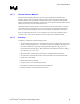
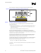
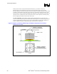
Figure 2 illustrates the combination of the different thermal characterization parameters.
Figure 2. Processor Thermal characterization parameter Relationships
HEATSINK
IHS
TIM
PROCESSOR
T
S
T
C
T
A
SOCKET
Ψ
ΨΨ
Ψ
SA
Ψ
ΨΨ
Ψ
CS
Ψ
ΨΨ
Ψ
CA
HEATSINK
IHS
TIM
PROCESSOR
T
S
T
C
T
A
SOCKET
Ψ
ΨΨ
Ψ
SA
Ψ
ΨΨ
Ψ
CS
Ψ
ΨΨ
Ψ
CA
3.2.2.4 Example of Heatsink Performance Evaluation
The cooling performance Ψ
CA
is then defined using the notion of thermal characterization
parameter described above:
• Define a target case temperature T
C-MAX,F
and corresponding thermal design power TDP
F
at a
target frequency given in the Intel
®
Pentium
®
4 Processor with 512-KB L2 Cache on 0.13
Micron Process Datasheet.
• Define a target local ambient temperature around the processor, T
A
.
Since the processor thermal specifications (T
C-MAX
and TDP) can vary with the processor
frequency, it may be important to identify the worse case (smallest Ψ
CA
) for a targeted chassis
(characterized by T
A
) to establish a design strategy such that a given heatsink can meet the thermal
requirements of a given range of processor frequencies.
The following provides an illustration of how one might determine the appropriate performance
targets. The power and temperature numbers used here are not related to any Intel processor
thermal specifications, and are given only to carry out the example.
Assume the TDP is 90W and the case temperature specification is 70 °C. Assume as well that the
system airflow has been designed such that the local ambient temperature is 38°C. Then the
following could be calculated using equation 1 from above:
Ψ
CA
= (T
CMAX,F
- T
A
) / TDP
F
= (70 – 38) / 90 = 0.36 °C/W
Assuming Ψ
CS
= 0.08 °C/W, solving for equation 2 from above, the performance of the heatsink
itself has to be:
Ψ
SA
= Ψ
CA
− Ψ
CS
= 0.36 − 0.08 = 0.28 °C/W