
Intel Pentium 4 Processor with 512-KB L2 Cache on 0.13 Micron Process Thermal Design Guidelines


Thermal Specifications
R
20 Intel
®
Pentium
®
4 Processor Thermal Design Guide
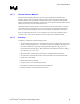
memory cards, AGP card, chipset heatsink, and hard drive(s). If a barrier is used, the
thermocouple can be taped directly to the barrier at the horizontal locations as previously
described, half way between the fan hub and the fan housing. If a variable speed fan is used, it may
be useful to add a thermocouple taped to the barrier above the location of the temperature sensor
used by the fan to check its speed setting against air temperature. When measuring T
A
directly in a
chassis with a live motherboard, add-in cards and the other system components, it is likely that T
A
shows as highly non-uniform across the inlet fan section.
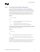
For passive heatsinks, thermocouples should be placed approximately 12.7 mm to 25.4 mm
(0.5 to 1.0 inches) away from processor heatsink as shown in Figure 4. The thermocouples should
be placed approximately 50.8 mm (2 inches ) above the baseboard. This placement guideline is
meant to minimize the effect of localized hot spots from baseboard components.
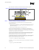
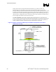
Figure 3. Guideline Locations for Measuring Local Ambient Temperature for an Active
Heatsink (not to scale)