
Intel Pentium 4 Processor with 512-KB L2 Cache on 0.13 Micron Process Thermal Design Guidelines


Thermal Specifications
R
22 Intel
®
Pentium
®
4 Processor Thermal Design Guide
3.3.3.1 Thermocouple Attachment
Thermocouples are often used to measure T
C
. Before any temperature measurements are made, the
thermocouples must be calibrated. This section describes the procedure for attaching a
thermocouple to the IHS for the case temperature (T
C
) measurement.
1. Obtain the necessary items needed for the quantity of thermocouple attaches desired:
• Fine point tweezers
• Exacto* knife (#11 blade)
• Thermocouples (Type K, 36 gauge, 36 inch, Teflon* insulation). Ensure that the
thermocouple has been properly calibrated
• 3M* Kapton* tape (or equivalent) cut into strips (1/8 inch X ½ inch)
• Epoxy (Omegabond* 101 or equivalent)
• Curing oven or equivalent.
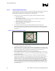
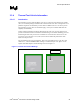
2. Use a scribe to mark at the center of the package (IHS side) where the bead of the
thermocouple will be placed. Determine the center of the package by drawing two diagonal
lines across the length of the package. The intersection of the two lines is the package center.
(See Figure 5).
Figure 5. Desired Thermocouple Location
3. After the marks are scribed, clean the desired thermocouple attach location with a mild
solvent and a lint-free wipe or cloth. Alcohol or acetone should suffice. Cleanliness of the part
is critical for a strong epoxy bond after curing.
4. With thermocouple (T/C) in hand, locate the junction and straighten the wire by hand so that
the first 4–6 inches are reasonably straight. Use the fine point tweezers to ensure that the bead
and the two protruding wires are straight and untwisted. Ensure the second layer of
thermocouple insulation, sometimes clear, is not covering the bead.
5. Place a slight downward bend (~30°) in the protruding wires approximately 1/16 inch from
junction using the tweezers. This aids the user in ensuring the thermocouple junction contacts
the heat spreader surface.
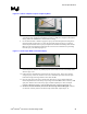
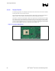
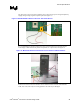
6. Place the thermocouple on the surface of the part so the bead is contacting the IHS at the
desired location. Hold the T/C with one hand and use a pair of tweezers to apply a cut piece
of Kapton*
tape across the wire approximately about ¼ inch back from the bead. Apply
pressure to the tape to ensure a good bond. Apply additional Kapton tape along the length of
the wire to ensure a good temporary bond to the part. (See following Figure 6). Check for
electrical continuity between the thermocouple and the IHS using a multimeter. If there
is no electrical continuity between the thermocouple and the IHS, remove the thermocouple
and repeat Steps 4–6.