
Intel Pentium 4 Processor with 512-KB L2 Cache on 0.13 Micron Process Thermal Design Guidelines


Thermal Specifications
R
Intel
®
Pentium
®
4 Processor Thermal Design Guide 23
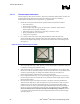
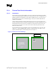
Figure 6. Location of Kapton* Tape for Temporary Bond
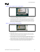
7. With the thermocouple temporarily held to the part, apply epoxy to the thermocouple bead for
a permanent bond. If applying Omegabond 101 epoxy, a small piece of paper works well for
mixing. Follow the manufacturer’s instructions for mixing.
8. Use the Exacto* knife or similar to apply the epoxy to the thermocouple bead. Dab glue on
the bead and the exposed wires. Use only the appropriate amount of epoxy to cement the
thermocouple to the IHS. Excess epoxy will prevent the heatsink from mating flush with the
IHS. The entire bead should be submerged and it is best to have insulated wires protruding
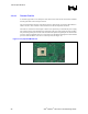
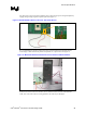
from the epoxy. (See following Figure 7).
Figure 7. Thermocouple Bead Covered with Epoxy
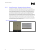
9. Add other tack-downs of epoxy along the length of wire to provide strain relief for the
thermocouple wire. Remove any small epoxy dots or lines that have been accidentally added
after the epoxy cures.
10. Follow the epoxy manufacturer’s instructions for curing the epoxy. If an oven is used for
curing the epoxy, ensure the vibration in the oven is minimal to prevent the thermocouple
bead from moving and losing intimate contact with the IHS.
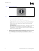
11. Once the epoxy has cured, remove all tape and check for any epoxy residual outside the
thermocouple attach area. Run the tip of your finger around the IHS surface to find any small
epoxy dots. Remove the non-necessary epoxy residual completely so it does not impact
heatsink to IHS mating surface. Clean the IHS surface after conducting this finger test.
12. Check for electrical continuity between the thermocouple and the IHS again. If there is
no electrical continuity between the thermocouple and the IHS, repeat Steps 4–12.