
Intel Pentium 4 Processor with 512-KB L2 Cache on 0.13 Micron Process Thermal Design Guidelines


Thermal Specifications
R
Intel
®
Pentium
®
4 Processor Thermal Design Guide 25
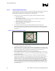
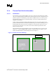
Figure 9. Heatsink Bottom Groove Dimensions
NOTES:
1. Applies to rectangular or cylindrical heatsink base
2. The groove depth (including the circle area) is 0.6 to 1.0 mm (0.025 to 0.040 inches)
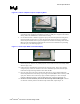
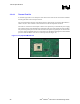
3.3.3.3 Heatsink Preparation – Radial (Cylindrical) Geometry
For some heatsinks that have a radial geometry (see Figure 10), it may be necessary to locate the
center of the heatsink using features in the fin pattern.
For example, the 62-fin radial heatsink of the Intel reference design for the Pentium 4 processor in
the 478-pin package described in the note below, requires the following procedure:
1. Identify fin gap (a) as shown in Figure 10.
2. Count ¼ of the total amount of fin gaps in clockwise direction; identify fin gap (b).
3. Repeat for fin gap (c) and fin gap (d).
4. Scribe lines (a-c) and (b-d) across the core area of the radial heatsink.
5. Locate heatsink center at the intersection of lines (a-c) and (b-d).
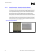
6. Machine a groove 1 mm (0.040 inches) wide, 0.6 mm (0.025 inches) deep along line (o-a).
7. Locate the center for the circle area 1.3 mm (0.050 inches) off the heatsink centerline, along
line (o-a).
8. Machine the circle area 4.5 mm (0.180 inches) diameter, 0.6 mm (0.025 inches) deep to
accommodate the thermocouple and epoxy bead.
Note: This procedure takes into account the fact that the center of the IHS and the center of the heatsink
coincide for this particular design.