
Intel Pentium 4 Processor with 512-KB L2 Cache on 0.13 Micron Process Thermal Design Guidelines


Thermal Specifications
R
26 Intel
®
Pentium
®
4 Processor Thermal Design Guide
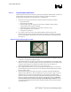
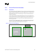
Figure 10. Radial Heatsink Geometry
a
b
c
d
o
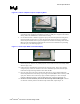
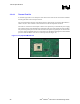
3.3.3.4 Thermal Measurement
1. Attach a thermocouple at the center of the package (IHS-side) using the proper thermocouple
attach procedure (refer to Section 3.3.3.1).
2. Connect the thermocouple to a thermocouple meter.
3. Mill groove on heatsink base (refer to Section 3.3.3.2 or to Section 3.3.3.3).
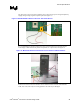
4. Apply thermal interface material to either IHS top surface or on the surface of heatsink base.
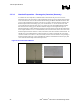
5. Mount the heatsink to the processor package with the intended heatsink attach clip and all
relevant mechanical interface components (e.g., retention mechanism, processor EMI
attenuation solutions, etc.).
6. Refer to Section 3.3.2 to setup the thermocouples used for T
A
measurement, and connect them
to a thermocouple meter.
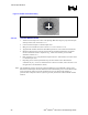
7. Depending on the overall experimental setup, the time needed to have stable thermal
conditions may vary. T
A
and T
C
measurements are valid once constant (refer to Section 3.3.4.4
for application to the thermal test vehicle).
Note: This methodology requires special care when assembling the grooved heatsink to the top of the
IHS with the thermocouple attached. Mismatch between the heatsink groove and the thermocouple
wires and bead may lead to inaccurate measurements, and even thermocouple damage, in
particular when compressive load is required to get better performance from the thermal interface
material.