
Intel Pentium 4 Processor with 512-KB L2 Cache on 0.13 Micron Process Thermal Design Guidelines


Thermal Specifications
R
30 Intel
®
Pentium
®
4 Processor Thermal Design Guide
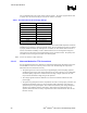
The recommended DC-power supply rating is listed in Table 1. The power supply should be able
to deliver more current if necessary to cover for die resistance variations.
Table 1. Recommended DC Power Supply Ratings
Target Die Power Level Power Supply Rating
20 W 40 V and 1 A
25 W 45 V and 1 A
30 W 45 V and 1 A
35 W 50 V and 1 A
40 W 55 V and 1 A
50 W 60 V and 1.5 A
60 W 65 V and 1.5 A
70 W 70 V and 1.5 A
75 W 75 V and 1.5 A
The power dissipation should be maintained at or below 75 W and the IHS temperature should be
maintained to less than 80°C during the thermal testing. The TTV should not be power on without
a properly installed heatsink. By violating these constraints, the TTV lifetime will be reduced. It
must be noted that the reliability of TTV is limited and the TTV is not designed for long-term
testing purposes. The heaters on the thermal testing devices are metal resistors. The polarity does
not matter: Positive and negative terminals are interchangeable.
Note: TTV is not sensitive to static electricity.
3.3.4.3 Alternate Method for TTV Connections
If a bare motherboard cannot be obtained, any motherboard designed for the Pentium 4 processor
with 512-KB L2 cache on 0.13 micron process can be used. The following the steps must be
followed for the TTV to function correctly.
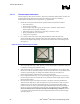
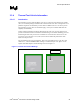
• The powering the TTV can be accessed by de-populating the power decoupling capacitors
and attaching wires to the power and ground sides of one of the capacitor. It is recommended
that all decoupling capacitors be removed because the high voltages required for the TTV
may exceed the maximum voltage rating of the capacitors.
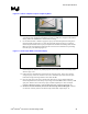
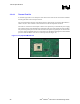
• The voltage regulator inductors should also be removed to isolate the VR from the TTV
power supply.
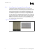
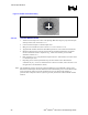
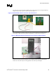
• The power and ground planes must be separated for the TTV to work properly. Therefore, the
motherboard schematics need to be used to determine what components need removed to
separate the power and ground planes. The resistance between the power and ground planes
should be open (infinite) with the socket empty. If the power and ground planes are not
separate, than not all of the necessary components have been removed and the TTV will not
function correctly.