
Intel Pentium 4 Processor with 512-KB L2 Cache on 0.13 Micron Process Thermal Design Guidelines

Thermal Specifications
R
Intel
®
Pentium
®
4 Processor Thermal Design Guide 31
3.3.4.4 Thermal Measurements
Refer to Section 3.3.2 for T
A
measurement methodology. Refer to Section 3.3.3.1 for
thermocouple attachment to the IHS and to Section 3.3.3.2 and Section 3.3.3.3 for the heatsink
preparation.
For TTV thermal measurement itself, use the following instructions, instead of the general thermal
measurement instructions given in Section 3.3.3.4:
1. Measure the resistance of the heater resistor of TTV at the room temperature to check for the
reasonable readings. If reasonable reading of ~60 W for the ITVN1 TTV and ~50 W for the
QELO TTV is not obtained the TTV may be damaged, the wire connection is not correct, or
the necessary board components have not been removed. In case a shortage occurs between
the positive and negative terminals, do not perform the test as damage could occur to the
power supply.
2. Attach a thermocouple at the center of the package (IHS-side) using the proper thermocouple
attach procedure (refer to Section 3.3.3.1).
3. Connect the thermocouple to a thermocouple meter.
4. Mill groove on heatsink base, as recommended in Section 3.3.3.2 and Section 3.3.3.3.
5. Apply thermal interface materials to either IHS top surface or the surface of heatsink base.
6. Mount the heatsink to the TTV with the intended heatsink attach clip and all relevant
mechanical interface components (e.g., retention mechanism, processor EMI attenuation
solutions, etc.).
7. Place the TTV in the test environment (e.g., a test bench, a wind tunnel or a computer
chassis).
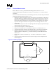
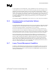
8. Connect the heater resistor of the TTV to a DC power supply. Connect voltage meters as
shown in Figure 15
Figure 15. TTV Wiring Diagram
I
R
shunt
R
heater
POWER SUPPLY
V
heater
V
shunt
+
-