
Intel Pentium 4 Processor with 512-KB L2 Cache on 0.13 Micron Process Thermal Design Guidelines


Thermal Specifications
R
32 Intel
®
Pentium
®
4 Processor Thermal Design Guide
9. Refer to Section 3.3.2 to setup the thermocouples used for T
A
measurement, and connect them
to a thermocouple meter.
10. Set the voltage of the DC power supply to the value calculated from the targeted power level
and the heater resistance, if the DC-power supplier uses a voltage-control mode
e.g.,
PowerResistanceHeaterVoltage ×=
. Alternatively, an appropriate current can be
set to the DC-power supplier if the DC-power supplier uses a current-control mode.
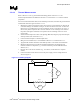
11. Calculate the actual power TDP applied to the heater resistor by multiplying the reading from
the voltage meter at the TTV with the current through the shunt resistor. The current through
the shunt resistor is calculated by dividing the reading from voltage meter at the shunt resistor
by the resistance of the shunt resistor. The shunt resistor is used to eliminate inaccuracies of
the current measurement through the TTV package. The location of each voltage meter is
shown in the figure in Step 8. As the heater heats up, the heater resistance will increase
slightly and the current will decrease resulting in a small drop of power if a voltage-control
mode is used. The power supply voltage has to be increased to compensate for the drop in the
current to maintain a constant power. Wait for one hour to reach the stable condition before
reading the case temperature (T
C
) and the local ambient temperature (T
A
) from the
thermocouple.
12. Calculate the case-to-ambient thermal characterization parameter resistance (Ψ
CA
) based on
equation 1 given in Section 3.2.2.3. This equation is shown below.
Ψ
CA
= (T
C
- T
A
) / TDP
3.3.4.5 TTV Correction Factor to the Intel
®
Pentium
®
4 Processor with
512-KB L2 Cache on 0.13 Micron Process
Correction factors usually need to be applied to predict the thermal solution performance on the
real processors arts from thermal performance measured on a thermal test vehicle. Table 2
provides these correction factors for the TTV used to simulate the Pentium 4 processor with
512-KB L2 cache on 0.13 micron process. The value of a thermal characterization parameter is
derived from the value measured on the TTV and the corresponding correction factor according to
the following equation:
{Processor Ψ
CA
} = {TTV Ψ
CA
} x Correction factor
This formula transposes to Ψ
CS
and Ψ
SA
.
Table 2. TTV Correction Factors
Thermal characterization
parameter
Correction Factor
Ψ
CS
1.151
Ψ
SA
1.014
Ψ
CA
1.053
Ψ
CA
correction factor should only be used when the ratio Ψ
CS
/Ψ
SA
is similar to the Intel reference
design (~ 0.53). If this ratio is significantly different, then it is recommended to use individual Ψ
CS
and Ψ
SA
correction factors and add corrected Ψ
CS
and Ψ
SA
to get Ψ
CA
.