
Intel Pentium 4 Processor with 512-KB L2 Cache on 0.13 Micron Process Thermal Design Guidelines


Thermal Specifications
R
Intel
®
Pentium
®
4 Processor Thermal Design Guide 33
3.4 Thermal Management Logic and Thermal Monitor
Feature
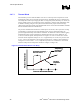
3.4.1 Processor Power Dissipation
An increase in processor operating frequency not only increases system performance, but also
increases the processor power dissipation. The relationship between frequency and power is
generalized in the following equation: P=CV
2
F (where P = power, C = capacitance, V = voltage,
F = frequency). From this equation, it is evident that power increases linearly with frequency and
with the square of voltage. In the absence of power saving technologies, ever increasing
frequencies will result in processors with power dissipations in the hundreds of Watts. Fortunately,
there are numerous ways to reduce the power consumption of a processor. Decreasing the voltage
and transistor size are two examples, a third is clock modulation, which is used extensively in
laptop designs.
Clock modulation is defined as periodically removing the clock signal from the processor core,
which effectively reduces its power consumption to a few Watts. A zero-Watt power dissipation
level is not achievable due to transistor leakage current and the need to keep a few areas of the
processor active (cache coherency circuitry, phase lock loops, interrupt recognition, etc.).
Therefore, by cycling the clocks on and off at a 50% duty cycle for example, the average power
dissipation can drop by up to 50%. Note that the processor performance also drops by about 50%
during this period, since program execution halts while the clocks are removed. Varying the duty
cycle has a corresponding influence on power dissipation and processor performance. The duty
cycle is specific to the processor (typically 30–50%).
Laptop systems use clock modulation to control system and processor temperatures. By using
various external measurement devices, laptops monitor the processor case temperature and turn on
fans or initiate clock modulation to reduce processor power dissipation and ensure that all
elements of the system operate within their temperature specifications. Unfortunately, using
external thermocouples connected to the processor package to monitor and control a thermal
management solution has some inherent disadvantages. Thermal conductivity through the
processor package creates a temperature gradient between the processor case and silicon. This
temperature difference may be large with the silicon temperature always being higher than the case
temperature. Since thermocouples measure case temperature, not silicon temperature, significant
added margin may be necessary to ensure the processor silicon does not exceed its maximum
specification (i.e., clock modulation may have to be turned on when the case temperature is
significantly below its maximum specification to ensure the processor does not overheat). This
added margin might have a substantial, and unacceptable, impact on system performance.
Thermal ramp rates, or change in die temperature over a specified time period (∆T/∆t), may be
extremely high in high power processors where ramp rates in excess of 50°C/s may occur in the
course of normal operation. With this type of thermal characteristic, it would not be possible to
control fans or other cooling devices based on processor case temperature. By the time the fans
have spun up to speed, the processor may be well beyond a safe operating temperature,. Just as
large added margins would be necessary to account for package thermal gradients, equally large
margins would also be necessary if temperature-controlled fans were implemented.
An on-die thermal management feature called Thermal Monitor is available on the Pentium 4
processor with 512-KB L2 cache on 0.13 micron process. This feature is the same as the one
found on the Pentium 4 processor. It provides a thermal management approach to support the
continued increases in processor frequency and performance. It resolves the issues discussed