
Intel Pentium 4 Processor with 512-KB L2 Cache on 0.13 Micron Process Thermal Design Guidelines


Thermal Specifications
R
34 Intel
®
Pentium
®
4 Processor Thermal Design Guide
above so that external thermocouples are no longer needed. By using an accurate on-die
temperature sensing circuit and a fast acting temperature control circuit, the processor can rapidly
initiate thermal management control. As a result, added thermal margins can be significantly
reduced and the resulting system performance impact can be minimized if not eliminated.
3.4.2 Thermal Monitor Implementation
On the Pentium 4 processor with 512-KB L2 cache on 0.13 micron process, the Thermal Monitor
is integrated into the processor silicon. The Thermal Monitor includes a highly accurate on-die
temperature sensing circuit, a signal (PROCHOT#) that indicates the processor has reached its
maximum operating temperature, registers to determine status, and a thermal control circuit that
can reduce processor temperature by controlling the duty cycle of the processor clocks. The
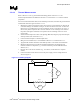
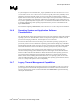
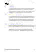
processor temperature is determined through an analog thermal sensor circuit comprised of a
temperature sensing diode, a factory calibrated reference current source, and a current comparator
(See Figure 16). A voltage applied across the diode will induce a current flow that varies with
temperature. By comparing this current with the reference current, the processor temperature can
be determined. The reference current source corresponds to the diode current when at the
maximum permissible processor operating temperature. Each processor is individually calibrated
during manufacturing to eliminate any potential manufacturing variations. Once configured, the
processor temperature at which the PROCHOT# signal is asserted (trip point) is not re-
configurable.
Figure 16. Thermal Sensor Circuit
PROCHOT#
Temperature sensing diode
Reference current source
Current comparator
The PROCHOT# signal is available internally to the processor as well as externally. External
indication of the processor temperature status is provided through the bus signal PROCHOT#.
When the processor temperature reaches the trip point, PROCHOT# is asserted. When the
processor temperature is below the trip point, PROCHOT# is deasserted. Assertion of the
PROCHOT# signal is independent of any register settings within the processor. It is asserted any
time the processor die temperature reaches the trip point. The point where the thermal control
circuit goes active is set to the same temperature at which the processor is tested.
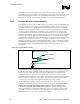
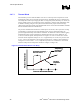
The Thermal Monitor’s thermal control circuit (TCC), when active, lowers the processor
temperature by reducing the duty cycle of the internal processor clocks. The thermal control
circuit portion of the Thermal Monitor must be enabled by the system BIOS for the
processor to be operating within specifications. When active, the TCC turns the processor
clocks off and then back on with a predetermined duty cycle. The actual duty cycle varies from
one product to another. Refer to Figure 17 for an illustration. Cycle times are processor speed
dependent and decrease as processor core frequencies increase.