
Mobile Intel Pentium 4 Processor - M and Intel 845MP/MZ Chipset Platform Design Guide


Mobile Intel
®
Pentium
®
4 Processor-M and Intel
®
845MP/845MZ Chipset Platform
100 Design Guide
R
9. I/O Subsystem
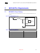
9.1. IDE Interface
This section contains guidelines for connecting and routing the ICH3-M IDE interface. The ICH3-M has
two independent IDE channels. This section provides guidelines for IDE connector cabling and
motherboard design, including component and resistor placement, and signal termination for both IDE
channels. The ICH3-M has integrated the series resistors that have been typically required on the IDE
data signals (PDD[15:0] and SDD[15:0]) running to the two ATA connectors. Additional series
termination resistors may be needed; the designer should verify motherboard signal integrity through
simulation. Zero Ohm series resistors can be added into the design as a stuffing option to address
possible noise issues on the motherboard.
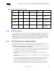
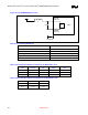
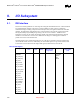
The IDE interface can be routed with 4-mil traces on 7-mil spaces, and must be less than 8 inches long
(from ICH3-M to IDE connector). Additionally, the shortest IDE signal (on a given IDE channel) must
be less than 0.5 inches shorter than the longest IDE signal (on that channel). See Table 38.
Table 38. IDE Signals
Signal Max length
(inch)
Width
(mils)
Space
(mils)
Relative
Mismatch max
length (mils)
Relative To Space with
other signals
(mils)
Signal
Group#ide1
IDE_PDD[15:0]
IDE_SDD[15:0]
IDE_PDA2
IDE_PDCS3#
IDE_PATADET
IDE_SATADET
IDE_SEC_RST#
IDE_PRI_RST#
IDE_PDA0
IDE_PDA1
IDE_PDCS1#
IDE_PDDACK#
IDE_PDDREQ
IDE_PDIOW#
IDE_SDA0
IDE_SDA1
IDE_SDA2
IDE_SDCS1#
8 4 7 ±250 Shortest and
longest IDE
signal in
same
channel
8